This describes the mapping between Boolean alarm signals and wires in each cable.
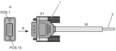
BTS30/312
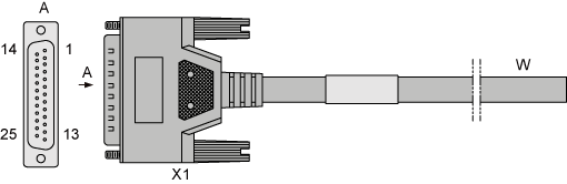
The extension alarm cables are routed from the EAC1 and EAC2 ports on top of the cabinet. It is used to collect the external extension alarm information. The extension alarm cables can be classified into extension alarm cable A and extension alarm cable B.
Cable |
X1 End |
Wire Type |
Wire Color |
Signal Type |
|---|---|---|---|---|
W.1 |
X1.1 |
Twisted pair |
PINK(1 RED DOT) |
FIRE_ALM |
W.2 |
X1.2 |
PINK(1 BLACK DOT) |
SMOKE_ALM |
|
W.3 |
X1.3 |
Twisted pair |
ORANGE(1 RED DOT) |
BREAK_ALM |
W.4 |
X1.4 |
ORANGE(1 BLACK DOT) |
FLOOD_ALM |
|
W.5 |
X1.5 |
Twisted pair |
GREEN(1 RED DOT) |
UPTEM_ALM |
W.6 |
X1.6 |
GREEN(1 BLACK DOT) |
DOWN_ALM |
|
W.7 |
X1.7 |
Twisted pair |
BLUE(1 RED DOT) |
HUM_ALM |
W.8 |
X1.8 |
BLUE(1 BLACK DOT) |
AIRC_ALM |
|
W.9 |
X1.9 |
Twisted pair |
GRAY(1 RED DOT) |
GND01 |
W.10 |
GRAY(1 BLACK DOT) |
|||
W.11 |
Twisted pair |
PINK(2 RED DOT) |
||
W.12 |
PINK(2 BLACK DOT) |
|||
W.13 |
- |
ORANGE(2 RED DOT) |
||
W.14 |
X1.22 |
Twisted pair |
GREEN(2 RED DOT) |
GND03 |
W.15 |
GREEN(2 BLACK DOT) |
|||
W.16 |
Twisted pair |
BLUE(2 RED DOT) |
||
W.17 |
BLUE(2 RED DOT) |
|||
W.18 |
- |
GRAY(2 RED DOT) |
||
W.19 |
X1.10 |
Twisted pair |
PINK(3 RED DOT) |
CBUS3_TD+ |
W.20 |
X1.11 |
PINK(3 BLACK DOT) |
CBUS3_TD- |
|
W.21 |
X1.12 |
Twisted pair |
ORANGE(3 RED DOT) |
CBUS3_RD+ |
W.22 |
X1.13 |
ORANGE(3 BLACK DOT) |
CBUS3_RD- |
|
W.23 |
X1.14 |
Twisted pair |
GREEN(3 RED DOT) |
BAK0 |
W.24 |
X1.15 |
GREEN(3 BLACK DOT) |
BAK1 |
|
W.25 |
X1.16 |
Twisted pair |
BLUE(3 RED DOT) |
BAK2 |
W.26 |
X1.17 |
BLUE(3 BLACK DOT) |
BAK3 |
|
W.27 |
X1.18 |
Twisted pair |
GRAY(3 RED DOT) |
BAK4 |
W.28 |
X1.19 |
GRAY(3 BLACK DOT) |
BAK5 |
|
W.29 |
X1.20 |
- |
PINK(4 RED DOT) |
BAK6 |
W.30 |
X1.21 |
Twisted pair |
ORANGE(4 RED DOT) |
GND02 |
W.31 |
ORANGE(4 BLACK DOT) |
|||
W.32 |
Twisted pair |
GREEN(4 RED DOT) |
||
W.33 |
GREEN(4 BLACK DOT) |
|||
W.34 |
- |
BLUE(4 RED DOT) |
||
W.35 |
X1.23 |
Twisted pair |
GRAY(4 RED DOT) |
- |
W.36 |
X1.24 |
GRAY(4 BLACK DOT) |
- |
|
W.37 |
X1.25 |
- |
PINK(FULL RED DOT) |
- |
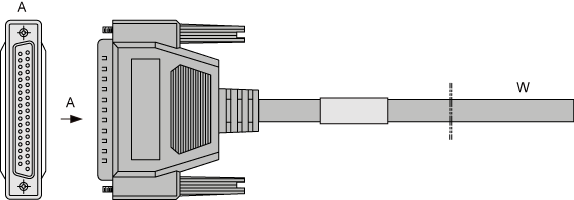
Cable |
X1 End |
Wire Type |
Wire Color |
Signal Type |
|---|---|---|---|---|
W.1 |
X1.1 |
Twisted pair |
PINK(FULL RED DOT) |
EAC_D_COM0 |
W.2 |
PINK(FULL BLACK DOT) |
|||
W.3 |
Twisted pair |
ORANGE(FULL RED DOT) |
||
W.4 |
ORANGE(FULL BLACK DOT) |
|||
W.5 |
Twisted pair |
GREEN(FULL RED DOT) |
||
W.6 |
X1.20 |
BLUE(FULL RED DOT) |
EAC_D_COM1 |
|
W.7 |
Twisted pair |
GRAY(4 RED DOT) |
||
W.8 |
GRAY(4 BLACK DOT) |
|||
W.9 |
Twisted pair |
PINK(1 RED DOT) |
||
W.10 |
PINK(1 BLACK DOT) |
|||
W.11 |
X1.2 |
Twisted pair |
ORANGE(1 RED DOT) |
EAC_OUT7 |
W.12 |
X1.21 |
ORANGE(1 BLACK DOT) |
EAC_OUT6 |
|
W.13 |
X1.3 |
Twisted pair |
GREEN(1 RED DOT) |
EAC_OUT5 |
W.14 |
X1.22 |
GREEN(2 RED DOT) |
EAC_OUT4 |
|
W.15 |
X1.4 |
Twisted pair |
GREEN(2 BLACK DOT) |
EAC_OUT3 |
W.16 |
X1.23 |
BLUE(2 RED DOT) |
EAC_OUT2 |
|
W.17 |
X1.5 |
Twisted pair |
BLUE(2 RED DOT) |
EAC_OUT1 |
W.18 |
X1.24 |
GRAY(2 RED DOT) |
EAC_OUT1 |
|
W.19 |
X1.6 |
Twisted pair |
PINK(3 RED DOT) |
EAC_IN1 |
W.20 |
X1.25 |
PINK(3 BLACK DOT) |
EAC_IN_UNUSE14 |
|
W.21 |
X1.7 |
Twisted pair |
ORANGE(3 RED DOT) |
EAC_IN_UNUSE12 |
W.22 |
X1.26 |
ORANGE(3 BLACK DOT) |
EAC_IN_UNUSE10 |
|
W.23 |
X1.8 |
Twisted pair |
GREEN(3 RED DOT) |
EAC_IN_UNUSE8 |
W.24 |
X1.27 |
GREEN(3 BLACK DOT) |
EAC_IN_UNUSE6 |
|
W.25 |
X1.9 |
Twisted pair |
BLUE(2 RED DOT) |
EAC_IN_UNUSE4 |
W.26 |
X1.28 |
BLUE(2 BLACK DOT) |
EAC_IN_UNUSE2 |
|
W.27 |
X1.10 |
Twisted pair |
GRAY(2 RED DOT) |
EAC_IN_UNUSE0 |
W.28 |
X1.29 |
GRAY(2 BLACK DOT) |
EAC_D_COM0 |
|
W.29 |
X1.11 |
Twisted pair |
PINK(3 RED DOT) |
EAC_D_COM0 |
W.30 |
X1.30 |
PINK(3 BLACK DOT) |
EAC_D_COM1 |
|
W.31 |
X1.12 |
Twisted pair |
ORANGE(3 RED DOT) |
EAC_D_COM1 |
W.32 |
X1.31 |
ORANGE(3 BLACK DOT) |
EAC_A_COM0 |
|
W.33 |
X1.13 |
Twisted pair |
GREEN(3 RED DOT) |
EAC_A_COM1 |
W.34 |
X1.32 |
GREEN(3 BLACK DOT) |
EAC_A_IN7 |
|
W.35 |
X1.14 |
Twisted pair |
BLUE(3 RED DOT) |
EAC_A_IN6 |
W.36 |
X1.33 |
BLUE(3 BLACK DOT) |
EAC_A_IN5 |
|
W.37 |
X1.15 |
Twisted pair |
GRAY(3 RED DOT) |
EAC_A_IN4 |
W.38 |
X1.34 |
GRAY(3 BLACK DOT) |
EAC_A_COM2 |
|
W.39 |
X1.16 |
Twisted pair |
PINK(4 RED DOT) |
EAC_A_COM3 |
W.40 |
X1.35 |
PINK(4 BLACK DOT) |
EAC_A_IN3 |
|
W.41 |
X1.17 |
Twisted pair |
ORANGE(4 RED DOT) |
EAC_A_IN2 |
W.42 |
X1.36 |
ORANGE(4 BLACK DOT) |
EAC_A_IN1 |
|
W.43 |
X1.18 |
Twisted pair |
GREEN(4 RED DOT) |
EAC_A_IN0 |
W.44 |
X1.37 |
GREEN(4 BLACK DOT) |
EAC_A_COM4 |
|
W.45 |
X1.19 |
- |
BLUE(4 RED DOT) |
EAC_A_COM5 |
BTS3002C
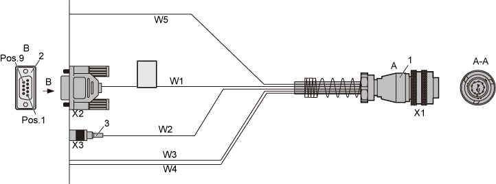
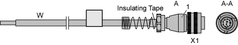
(1) Cylindrical waterproof connector |
(2) DB9 terminal |
(3) SMB terminal |
Cable |
Cylindrical waterproof connector |
The Other End |
Wire Color |
Signal Type |
|---|---|---|---|---|
W5 |
X1.1 |
- |
Purple |
RS485 TX+ |
W5 |
X1.2 |
White |
RS485 TX- |
|
W5 |
X1.3 |
Yellow |
RS485 RX+ |
|
W5 |
X1.4 |
Green |
RS485 RX- |
|
W1 |
X1.5 |
X2.1 |
White |
- |
W1 |
X1.5 |
X2.2 |
White |
- |
W1 |
X1.5 |
X2.3 |
White |
- |
W2 |
X1.5 |
X3.Ring |
- |
- |
W2 |
X1.6 |
X3.Tip |
- |
- |
W1 |
X1.7 |
X2.6 |
Blue |
- |
W1 |
X1.8 |
X2.8 |
Orange |
- |
W1 |
X1.9 |
X2.7 |
Green |
- |
W3 |
X1.10 |
- |
- |
- |
W4 |
X1.11 |
- |
- |
- |
W1 |
X1.12 |
X2.Shell |
braid |
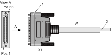
BTS3012
X1 End |
Wire Type |
Wire Color |
Alarm Output Serial Number |
|---|---|---|---|
X1.1 |
Twisted pair |
White |
Alarm output 1 |
X1.2 |
Blue |
||
X1.3 |
Twisted pair |
White |
Alarm output 2 |
X1.4 |
Orange |
||
X1.6 |
Twisted pair |
White |
Alarm output 3 |
X1.7 |
Green |
||
X1.8 |
Twisted pair |
White |
Alarm output 4 |
X1.9 |
Brown |
||
X1.11 |
Twisted pair |
White |
Alarm output 5 |
X1.12 |
Gray |
||
X1.13 |
Twisted pair |
Red |
Alarm output 6 |
X1.14 |
Blue |
X1 End |
Wire Type |
Core Color |
Alarm Input Serial Number |
|---|---|---|---|
X1.2 |
Twisted pair |
White |
Alarm input 1 |
X1.36 |
Blue |
||
X1.3 |
Twisted pair |
White |
Alarm input 2 |
X1.37 |
Orange |
||
X1.4 |
Twisted pair |
White |
Alarm input 3 |
X1.38 |
Green |
||
X1.5 |
Twisted pair |
White |
Alarm input 4 |
X1.39 |
Brown |
||
X1.6 |
Twisted pair |
White |
Alarm input 5 |
X1.40 |
Gray |
||
X1.7 |
Twisted pair |
Red |
Alarm input 6 |
X1.41 |
Blue |
||
X1.8 |
Twisted pair |
Red |
Alarm input 7 |
X1.42 |
Orange |
||
X1.9 |
Twisted pair |
Red |
Alarm input 8 |
X1.43 |
Green |
||
X1.10 |
Twisted pair |
Red |
Alarm input 9 |
X1.44 |
Brown |
||
X1.11 |
Twisted pair |
Red |
Alarm input 10 |
X1.45 |
Gray |
||
X1.12 |
Twisted pair |
Black |
Alarm input 11 |
X1.46 |
Blue |
||
X1.13 |
Twisted pair |
Black |
Alarm input 12 |
X1.47 |
Orange |
||
X1.14 |
Twisted pair |
Black |
Alarm input 13 |
X1.48 |
Green |
||
X1.15 |
Twisted pair |
Black |
Alarm input 14 |
X1.49 |
Brown |
||
X1.16 |
Twisted pair |
Black |
Alarm input 15 |
X1.50 |
Gray |
||
X1.17 |
Twisted pair |
Yellow |
Alarm input 16 |
X1.51 |
Blue |
||
X1.18 |
Twisted pair |
White |
Alarm input 17 |
X1.52 |
Blue |
||
X1.19 |
Twisted pair |
White |
Alarm input 18 |
X1.53 |
Orange |
||
X1.20 |
Twisted pair |
White |
Alarm input 19 |
X1.54 |
Green |
||
X1.21 |
Twisted pair |
White |
Alarm input 20 |
X1.55 |
Brown |
||
X1.22 |
Twisted pair |
White |
Alarm input 21 |
X1.56 |
Gray |
||
X1.23 |
Twisted pair |
Red |
Alarm input 22 |
X1.57 |
Blue |
||
X1.24 |
Twisted pair |
Red |
Alarm input 23 |
X1.58 |
Orange |
||
X1.25 |
Twisted pair |
Red |
Alarm input 24 |
X1.59 |
Green |
||
X1.26 |
Twisted pair |
Red |
Alarm input 25 |
X1.60 |
Brown |
||
X1.27 |
Twisted pair |
Red |
Alarm input 26 |
X1.61 |
Gray |
||
X1.28 |
Twisted pair |
Black |
Alarm input 27 |
X1.62 |
Blue |
||
X1.29 |
Twisted pair |
Black |
Alarm input 28 |
X1.63 |
Orange |
||
X1.30 |
Twisted pair |
Black |
Alarm input 29 |
X1.64 |
Green |
||
X1.31 |
Twisted pair |
Black |
Alarm input 30 |
X1.65 |
Brown |
||
X1.32 |
Twisted pair |
Black |
Alarm input 31 |
X1.66 |
Gray |
||
X1.33 |
Twisted pair |
Yellow |
Alarm input 32 |
X1.67 |
Blue |
X1 End |
Wire Type |
Wire Color |
Alarm Output Serial Number |
|---|---|---|---|
X1.1 |
Twisted pair |
White |
Alarm input 3 |
X1.10 |
Blue |
||
X1.2 |
Twisted pair |
White |
Alarm input 4 |
X1.11 |
Orange |
||
X1.3 |
Twisted pair |
White |
Alarm input 5 |
X1.12 |
Green |
||
X1.4 |
Twisted pair |
White |
Alarm input 6 |
X1.13 |
Brown |
||
X1.5 |
Twisted pair |
White |
Alarm input 7 |
X1.14 |
Gray |
||
X1.6 |
Twisted pair |
Red |
Alarm input 8 |
X1.15 |
Blue |
||
X1.7 |
Twisted pair |
Red |
Alarm output 4 |
X1.16 |
Green |
||
X1.8 |
Twisted pair |
Red |
Alarm output 3 |
X1.25 |
Green |
||
X1.18 |
Twisted pair |
Red |
Alarm output 1 |
X1.26 |
Brown |
||
X1.9 |
Twisted pair |
Red |
Alarm output 2 |
X1.17 |
Gray |
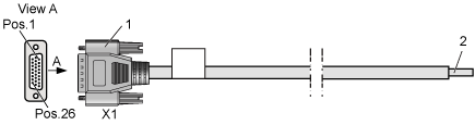
BTS3012AE
X1 End |
Wire Type |
Wire Color |
Alarm Input Serial Number |
|---|---|---|---|
X1.1 |
Twisted pair |
Blue |
Alarm input 6 (provided by the DTMU) |
X1.17 |
White |
||
X1.2 |
Twisted pair |
Orange |
Alarm input 2 (provided by the DTMU) |
X1.18 |
White |
||
X1.3 |
Twisted pair |
Green |
Alarm input 1 (provided by the DTMU) |
X1.19 |
White |
||
X1.4 |
Twisted pair |
Brown |
Alarm input 4 (provided by the DTMU) |
X1.20 |
White |
||
X1.5 |
Twisted pair |
Gray |
Alarm input 3 (provided by the DTMU) |
X1.21 |
White |
||
X1.6 |
Twisted pair |
Blue |
Alarm input 5 (provided by the DTMU) |
X1.22 |
Red |
||
X1.7 |
Twisted pair |
Orange |
Alarm input 7 (provided by the DTMU) |
X1.23 |
Red |
||
X1.8 |
Twisted pair |
Green |
Alarm input 1 (provided by the NPMI) |
X1.38 |
Red |
||
X1.9 |
Twisted pair |
Brown |
Alarm input 8 (provided by the DTMU) |
X1.24 |
Red |
||
X1.10 |
Twisted pair |
Gray |
Alarm input 2 (provided by the NPMI) |
X1.25 |
Red |
||
X1.11 |
Twisted pair |
Blue |
Alarm input 5 (provided by the NPMI) |
X1.26 |
Black |
||
X1.12 |
Twisted pair |
Orange |
Alarm input 4 (provided by the NPMI) |
X1.27 |
Black |
||
X1.13 |
Twisted pair |
Green |
Alarm input 6 (provided by the NPMI) |
X1.28 |
Black |
||
X1.14 |
Twisted pair |
Brown |
Alarm input 7 (provided by the NPMI) |
X1.29 |
Black |
||
X1.34 |
Twisted pair |
Gray |
- |
X1.35 |
Black |
||
X1.36 |
Twisted pair |
Blue |
- |
X1.37 |
Yellow |
||
Shell |
Shield |
- |
- |
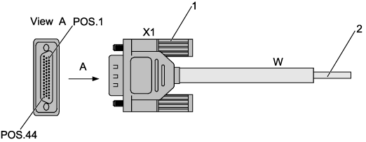
BTS3006C/BTS3002E
The BTS3006C/BTS3002E external alarm cable is used to connect the external alarm equipment and to monitor the power status and environment status through the DMCM.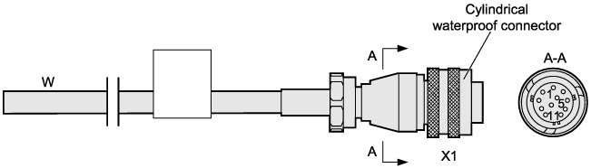
Wire |
Pin at X1 End |
Wire Color |
Remarks on Twisted Pair Cable |
|---|---|---|---|
W |
X1.1 |
Blue |
TX+ |
Red/blue |
|||
X1.2 |
Orange |
TX- |
|
Red/orange |
|||
X1.3 |
Green |
RX+ |
|
Green/Red |
|||
X1.4 |
Brown |
RX- |
|
Red/brown |
|||
X1.5 |
White/blue |
GND |
|
X1.7 |
Blue |
G1 |
|
X1.5 |
White/orange |
GND |
|
X1.8 |
Orange |
G2 |
|
X1.11 |
White/green |
GND |
|
X1.9 |
Green |
G3 |
|
X1.11 |
White/brown |
GND |
|
X1.10 |
Brown |
G4 |
BTS3900/BTS3900A/DBS3900
The BBU alarm cable is used to transmit alarm signals from external equipment to the BBU3900.The BBU alarm cable has an RJ-45 connector at each end, as shown in Figure 10. One RJ-45 connector at one end, however, may be removed and an appropriate terminal may be added according to the field requirements.
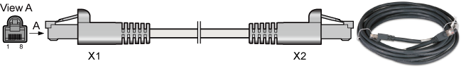
Table 10 shows the wire sequence of the BBU alarm cable.
BBU Alarm Port |
Wire Color |
Description |
|---|---|---|
EXT-ALM1 |
White and orange/Orange |
Boolean value input 5+/Boolean value input 5- (GND) |
White and green/Green |
Boolean value input 6+/Boolean value input 6- (GND) |
|
White and blue/Blue |
Boolean value input 7+/Boolean value input 7- (GND) |
|
White and brown/Brown |
Boolean value input 8+/Boolean value input 8- (GND) |
|
EXT-ALM0 |
White and orange/Orange |
Boolean value input 1+/Boolean value input 1- (GND) |
White and green/Green |
Boolean value input 2+/Boolean value input 2- (GND) |
|
White and blue/Blue |
Boolean value input 3+/Boolean value input 3- (GND) |
|
White and brown/Brown |
Boolean value input 4+/Boolean value input 4- (GND) |