The components on the front panel of the GBAM are the CD drive, LEDs, ports, and switches.
Figure 1 shows the front panel of the GBAM.
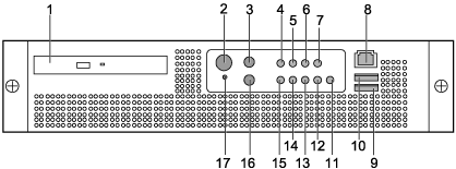
Table 1 describes the silkscreens on the front panel of the GBAM.
SN |
Silkscreen |
Description |
|---|---|---|
1 |
None |
CD-ROM drive |
2 |
|
Power switch |
3 |
|
Reset switch |
4 |
CRT |
The CRT LED indicates the critical alarm information. When the indicator is on (yellow), a critical fault occurs in the system and the system cannot work properly. |
5 |
MJR |
The MJR LED indicates the major alarm information. When the indicator is on (yellow), a major fault occurs in the system. Though the system can work properly, its performance deteriorates. |
6 |
MNR |
The MNR LED indicates the minor alarm information. When the indicator is on (yellow), a minor fault occurs in the system. The system can still work properly. |
7 |
PWR |
The PWR LED indicates the power fault information. When the indicator is on (yellow), the power supply for the system is faulty. |
8 |
|
Serial port, with an 8-pin RJ45 connector |
9 |
|
USB port |
10 |
||
11 |
|
Indicates the status of the read and write function of hard disk 2. When the LED is green, the read and write function of the hard disk is normal; when the LED is yellow, the read and write function of the hard disk is not normal. |
12 |
|
Indicates the status of the read and write function of hard disk 1. When the LED is green, the read and write function of the hard disk is normal; when the LED is yellow, the read and write function of the hard disk is not normal. |
13 |
ON |
Main power LED |
14 |
|
NIC0/NIC1 LED |
15 |
|
System ID LED |
16 |
|
ID switch, used to switch the system ID. |
17 |
None |
NMI switch. When the NMI switch is pressed, the GBAM is in the pause state and continues to diagnose faults. |


