The active/standby 75-ohm coaxial cable is a type of E1/T1 cables. The number of active/standby 75-ohm coaxial cables to be configured depends on site requirements. It transmits E1 signals. It is used to connect the GEIUA/GEIUB/GEIUP/GEIUT/GEHUB/GEPUG to the DDF or other NEs.
Cable Structure
The active/standby 75-ohm coaxial cable has 2x8 wires. That is, two active/standby 75-ohm coaxial cables form one group and each cable contains eight micro coaxial cables. The 16 micro coaxial cables bear eight E1 RX and TX links.
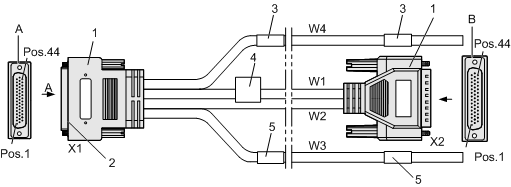
Figure 1 shows the active/standby 75-ohm coaxial cable.

(1) DB44 connector |
(2) Shell (metal shell of the DB44 connector) |
(3) Label 1 (identifying one coaxial cable) |
(4) Main label (identifying the BOM code, version, and information about the cable manufacturer) |
(5) Label 2 (identifying one coaxial cable) |
As shown in Figure 1, W3 and W4 are 75-ohm coaxial cables; W1 and W2 are 100-ohm twisted pair cables; X1 and X2 are DB44 connectors, which should be connected to the active/standby GEIUA/GEIUB/GEIUP/GEIUT/GEHUB/GEPUG.
Table 1 describes the mapping between the active/standby 75-ohm coaxial cable and the pins of the DB44 connector.
X1 |
W3 |
Remarks |
X1 |
W4 |
Remarks |
||
|---|---|---|---|---|---|---|---|
Pin of DB44 Connector |
Signal |
Micro Coaxial Cable |
Pin of DB44 Connector |
Signal |
Micro Coaxial Cable |
||
38 |
Ring |
1 |
R1 |
15 |
Ring |
1 |
T1 |
23 |
Tip |
30 |
Tip |
||||
37 |
Ring |
2 |
R2 |
14 |
Ring |
2 |
T2 |
22 |
Tip |
29 |
Tip |
||||
36 |
Ring |
3 |
R3 |
13 |
Ring |
3 |
T3 |
21 |
Tip |
28 |
Tip |
||||
35 |
Ring |
4 |
R4 |
12 |
Ring |
4 |
T4 |
20 |
Tip |
27 |
Tip |
||||
34 |
Ring |
5 |
R5 |
11 |
Ring |
5 |
T5 |
19 |
Tip |
26 |
Tip |
||||
33 |
Ring |
6 |
R6 |
10 |
Ring |
6 |
T6 |
18 |
Tip |
25 |
Tip |
||||
32 |
Ring |
7 |
R7 |
9 |
Ring |
7 |
T7 |
17 |
Tip |
24 |
Tip |
||||
31 |
Ring |
8 |
R8 |
8 |
Ring |
8 |
T8 |
16 |
Tip |
7 |
Tip |
||||
Shell |
Outer Braid of Whole Cable |
Shell |
Outer Braid of Whole Cable |
||||
As listed in Table 1, T1 indicates the first-route TX link, and R1 indicates the first-route RX link. Similarly, RN indicates the Nth-route RX link, and TN indicates the Nth-route TX link.
Table 2 describes the signals of the micro coaxial cables listed in Table 1.
Signal Label |
Bearing Media |
|---|---|
Ring |
Shielding layer of the coaxial cable |
Tip |
Wire of the coaxial cable |
Table 3 describes the mapping between the 100-ohm twisted pair cables (W1 and W2) and the pins of the DB44 connector.
W2 |
W1 |
||||
|---|---|---|---|---|---|
Pin of X1 Connector |
Pin of X2 Connector |
Remarks |
Pin of X1 Connector |
Pin of X2 Connector |
Remarks |
38 |
38 |
PAIR |
15 |
15 |
PAIR |
23 |
23 |
30 |
30 |
||
37 |
37 |
PAIR |
14 |
14 |
PAIR |
22 |
22 |
29 |
29 |
||
36 |
36 |
PAIR |
13 |
13 |
PAIR |
21 |
21 |
28 |
28 |
||
35 |
35 |
PAIR |
12 |
12 |
PAIR |
20 |
20 |
27 |
27 |
||
34 |
34 |
PAIR |
11 |
11 |
PAIR |
19 |
19 |
26 |
26 |
||
33 |
33 |
PAIR |
10 |
10 |
PAIR |
18 |
18 |
25 |
25 |
||
32 |
32 |
PAIR |
9 |
9 |
PAIR |
17 |
17 |
24 |
24 |
||
31 |
31 |
PAIR |
8 |
8 |
PAIR |
16 |
16 |
7 |
7 |
||
Shell |
Shell |
Braid |
Shell |
Shell |
Braid |
As listed in Table 3, PAIR indicates a pair of twisted pair cables, and Braid indicates the outer shielding layer of the twisted pair cable.
Installation Position
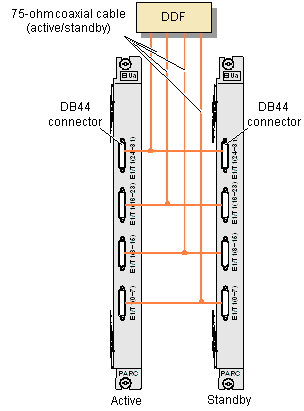
The two DB44 connectors at one end of the active/standby 75-ohm coaxial cable are fixed to the active and standby boards (GEIUA/GEIUB/GEIUP/GEIUT/GEHUB/GEPUG. The other end of the 75-ohm active/standby coaxial cable is connected to the DDF, and then to other NEs through a transmission device. Alternatively, the other end of the 75-ohm active/standby coaxial cable is directly connected to an NE.
Figure 2 shows the installation position of the active/standby 75-ohm coaxial cable.
