The active/standby 120-ohm twisted pair cable is a type of E1/T1 cable. The number of active/standby 120-ohm twisted pair cables to be configured depends on site requirements. It transmits E1/T1 signals. It is used to connect the GEIUA/GEIUB/GEIUP/GEIUT/GEHUB/GEPUG to the DDF or other NEs.
Cable Structure
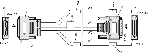
Figure 1 shows the active/standby 120-ohm twisted pair cable.

(1) DB44 connector |
(2) Shell (metal shell of the DB44 connector) |
(3) Label 1 (identifying one twisted pair cable) |
(4) Main label (identifying the BOM code, version, and manufacturer information about the cable) |
(5) Label 2 (identifying one twisted pair cable) |
As shown in Figure 1, W3 and W4 are 120-ohm twisted pair cables; W1 and W2 are 100-ohm twisted pair cables; X1 and X2 are DB44 connectors, which should be connected to the active and standby boards.
Table 1 describes the mapping between the active/standby 120-ohm twisted pair cable and the pins of the DB44 connector.
X1 |
W3 |
Color |
X1 |
W4 |
Color |
||
|---|---|---|---|---|---|---|---|
Pin of DB44 Connector |
Signal |
Identifier of Twisted Pair Wire |
Pin of DB44 Connector |
Signal |
Identifier of Twisted Pair Wire |
||
38 |
Ring/R- |
R1 |
Blue |
15 |
Ring/R- |
T1 |
Blue |
23 |
Tip/R+ |
White |
30 |
Tip/R+ |
White |
||
37 |
Ring/R- |
R2 |
Orange |
14 |
Ring/R- |
T2 |
Orange |
22 |
Tip/R+ |
White |
29 |
Tip/R+ |
White |
||
36 |
Ring/R- |
R3 |
Green |
13 |
Ring/R- |
T3 |
Green |
21 |
Tip/R+ |
White |
28 |
Tip/R+ |
White |
||
35 |
Ring/R- |
R4 |
Brown |
12 |
Ring/R- |
T4 |
Brown |
20 |
Tip/R+ |
White |
27 |
Tip/R+ |
White |
||
34 |
Ring/T- |
R5 |
Gray |
11 |
Ring/T- |
T5 |
Gray |
19 |
Tip/T+ |
White |
26 |
Tip/T+ |
White |
||
33 |
Ring/T- |
R6 |
Blue |
10 |
Ring/T- |
T6 |
Blue |
18 |
Tip/T+ |
Red |
25 |
Tip/T+ |
Red |
||
32 |
Ring/T- |
R7 |
Orange |
9 |
Ring/T- |
T7 |
Orange |
17 |
Tip/T+ |
Red |
24 |
Tip/T+ |
Red |
||
31 |
Ring/T- |
R8 |
Green |
8 |
Ring/T- |
T8 |
Green |
16 |
Tip/T+ |
Red |
7 |
Tip/T+ |
Red |
||
Shell |
Outer Braid of Whole Cable |
Shell |
Outer Braid of Whole Cable |
||||
In Table 1, either R- and R+ or T- and T+ stand for a pair of transmission and reception signals.
Table 2 describes the signals listed in Table 1.
Signal Label |
Bearing Media |
|---|---|
Ring/R- |
One wire of a twisted pair transmitting E1/T1 signals to the BSC |
Tip/R+ |
One wire of a twisted pair transmitting E1/T1 signals to the BSC |
Ring/T- |
One wire of a twisted pair transmitting E1/T1 signals from the BSC |
Tip/T+ |
One wire of a twisted pair transmitting E1/T1 signals from the BSC |
Table 3 describes the mapping between the 100-ohm twisted pair cables (W1 and W2) and the pins of the DB44 connector.
Twisted Pair Cable W2 |
Remarks |
Twisted Pair Cable W1 |
Remarks |
||
|---|---|---|---|---|---|
Pin of X1 Connector |
Pin of X2 Connector |
Pin of X1 Connector |
Pin of X2 Connector |
||
38 |
38 |
PAIR |
15 |
15 |
PAIR |
23 |
23 |
30 |
30 |
||
37 |
37 |
PAIR |
14 |
14 |
PAIR |
22 |
22 |
29 |
29 |
||
36 |
36 |
PAIR |
13 |
13 |
PAIR |
21 |
21 |
28 |
28 |
||
35 |
35 |
PAIR |
12 |
12 |
PAIR |
20 |
20 |
27 |
27 |
||
34 |
34 |
PAIR |
11 |
11 |
PAIR |
19 |
19 |
26 |
26 |
||
33 |
33 |
PAIR |
10 |
10 |
PAIR |
18 |
18 |
25 |
25 |
||
32 |
32 |
PAIR |
9 |
9 |
PAIR |
17 |
17 |
24 |
24 |
||
31 |
31 |
PAIR |
8 |
8 |
PAIR |
16 |
16 |
7 |
7 |
||
Shell |
Shell |
Braid |
Shell |
Shell |
Braid |
As listed in Table 3, PAIR indicates a pair of twisted pair cables, and Braid indicates the outer shielding layer of the twisted pair cable.
Installation Position
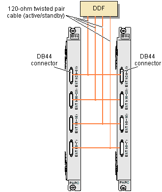
The two DB44 connectors at one end of the active/standby 120-ohm twisted pair cable are fixed to the active and standby boards (GEIUA/GEIUB/GEIUP/GEIUT/GEHUB/GEPUG). The other end of the active/standby 120-ohm twisted pair cable is connected to the DDF, and then to other NEs through a transmission device. Alternatively, the other end of the active/standby 120-ohm twisted pair cable is directly connected to an NE.
Figure 2 shows the installation position of the active/standby 120-ohm twisted pair cable.
