The straight-through cable is a mandatory Ethernet cable for the BSC. The number of straight-through cables to be configured depends on actual requirements.
- The GSCU to the GBAM
- The GBAM to the LAN switch
- The LAN switch to the M2000 (LAN)
- The LAN switch to the LMT computer of the BSC
- The LAN switch to the CBC
When the BSC is configured with the GOMU, the straight-through cable is used to connect:
- Connect the GSCUs in different subracks
- The GOMU to the LAN of the customer
- The GXPUM to the CBC
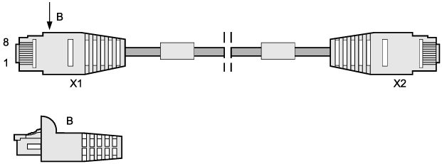
Pin Assignment
Table 1 describes the pins at both ends of the straight-through cable.
X1 End |
Wire Color | X2 End | Wire Color |
|---|---|---|---|
X1-1 |
White and orange |
X2-1 |
White and orange |
X1-2 |
Orange |
X2-2 |
Orange |
X1-3 |
White and green |
X2-3 |
White and green |
X1-4 |
Blue |
X2-4 |
Blue |
X1-5 |
White and blue |
X2-5 |
White and blue |
X1-6 |
Green |
X2-6 |
Green |
X1-7 |
White and brown |
X2-7 |
White and brown |
X1-8 |
Brown |
X2-8 |
Brown |
Installation Position (Configuration Type A)
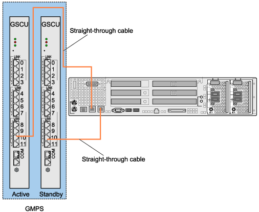
- When straight-through cables are used to connect the active and standby GSCUs in the GMPS to the GBAM, one end of one straight-through cable is connected to the active GSCU, and the other end of the cable is connected to one internal Ethernet port on the GBAM. (Both ends of each straight-through cable are RJ45 connectors.) One end of the other straight-through cable is connected to the standby GSCU, and the other end of the cable is connected to the other internal Ethernet port on the GBAM. Figure 2 shows the installation position of the straight-through cable.
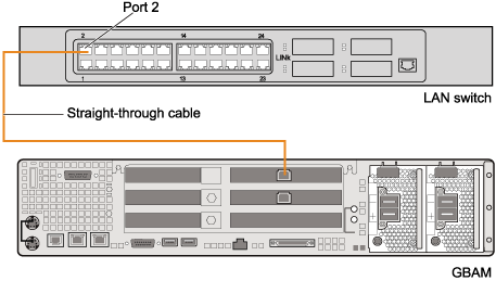
- When the straight-through cable is used to connect the GBAM to the LAN switch, one end of the cable is connected to port 2 on the LAN switch, and the other end of the cable is connected to an external Ethernet port on the GBAM. Figure 3 shows the installation position of the straight-through cable.
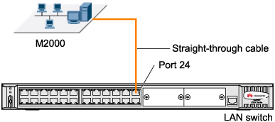
- When the straight-through cable is used to connect the LAN switch to the M2000 (LAN), one end of the cable is connected to port 24 on the LAN switch, and the other end of the cable is connected to the M2000 (LAN). Figure 4 shows the installation position of the straight-through cable.
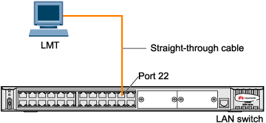
- When the straight-through cable is used to connect the LAN switch to the BSC LMT computer, one end of the cable is connected to port 22 on the LAN switch, and the other end of the cable is connected to the BSC LMT computer. Figure 5 shows the installation position of the straight-through cable.
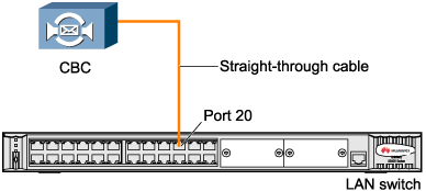
- When the straight-through cable is used to connect the LAN switch to the CBC, one end of the cable is connected to port 20 on the LAN switch, and the other end of the cable is connected to the corresponding Ethernet port of the CBC. Figure 6 shows the installation position of the straight-through cable.
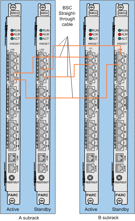
Installation Position (Configuration Type B)
- The Straight-through cable is used to connect the GSCUs in different subracks.
Figure 7 shows the installation position of the Straight-through cable.
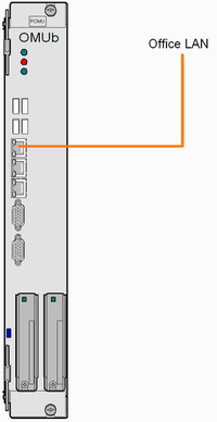
- When the straight-through cable is used to connect the GOMU to the LAN of the customer, one end of the cable is connected to port 0 or port 1 on the GOMU, and the other end of the cable is connected to the Ethernet port of the LAN of the customer.
Figure 8 shows the installation position of the straight-through cable.
 NOTE:
NOTE: The number of Ethernet cables used to connect the active and standby GOMUs to the LAN of the customer can be two or four, depending on the customer's requirement.
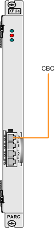
- When the straight-through cable is used to connect the GXPUM to the CBC, one end of the cable is connected to the Ethernet port on the GXPUM panel, and the other end of the cable is connected to an Ethernet port of the CBC. Figure 9 shows the installation position of the straight-through cable.