The physical boards of the GEHUB and GEPUG are the same. After being loaded with different software, the physical boards perform different functions. They have the same types of DIP switches: S2, S4, S6, S8, and S10.
Figure 1 shows the DIP switches on the GEHUB/GEPUG.
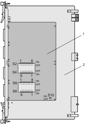
All the DIP switches are located on the front side of the sub-board, and cannot be directly observed since the sub-board is engaged to the bottom plate with its front side facing the bottom plate.
The DIP switches, S2, S4, S6, S8, and S10, are set from the side. As shown in Figure 1, a square opening is configured respectively between the S2 and the S4, and between the S8 and the S6 for the operator to operate these switches. Switch S10 is locates at the right lower corner of the sub-board, therefore it can be operated from the edge of the sub-board.
The DIP switches, S2, S4, S6, and S8, are used to set the protection grounding of the transmitting ends of E1/T1 links 0 to 31, and S10 is used to set the E1 balanced mode, E1 unbalanced mode, or T1 working mode. Table 1 and Table 2 describe S2, S4, S6, S8, and S10.
DIP Switch |
DIP Bit |
Description |
Switch Status |
Meaning |
|---|---|---|---|---|
S2 |
1-8 |
Used to set the protection grounding of the transmitting end of E1/T1 links 24-31 |
ON |
0 |
S4 |
1-8 |
Used to set the protection grounding of the transmitting end of E1/T1 links 16-23 |
ON |
0 |
S6 |
1-8 |
Used to set the protection grounding of the transmitting end of E1/T1 links 0-7 |
ON |
0 |
S8 |
1-8 |
Used to set the protection grounding of the transmitting end of E1/T1 links 8-15 |
ON |
0 |
S10 |
1-2 |
Work mode switch, consisting of two DIP bits. |
E1 unbalanced mode (ON, ON) |
(0, 0) |
DIP Switch |
DIP Bit |
Description |
Switch Status |
Meaning |
|---|---|---|---|---|
S2 |
1-8 |
Used to set the protection grounding of the transmitting end of E1/T1 links 24-31 |
OFF |
1 |
S4 |
1-8 |
Used to set the protection grounding of the transmitting end of E1/T1 links 16-23 |
OFF |
1 |
S6 |
1-8 |
Used to set the protection grounding of the transmitting end of E1/T1 links 0-7 |
OFF |
1 |
S8 |
1-8 |
Used to set the protection grounding of the transmitting end of E1/T1 links 8-15 |
OFF |
1 |
S10 |
1-2 |
Work mode switch, consisting of two DIP bits. |
E1 balanced mode (OFF, ON) |
(1, 0) |
T1 mode (ON, OFF) |
(0, 1) |
When the signals are transmitted through a 75-ohm coaxial cable in E1 unbalanced mode, set the DIP switch to ON and ground the TX end. When the signals are transmitted through a 120-ohm twisted pair cable in E1 balanced mode or T1 mode, set the DIP switch to OFF and do not ground the TX end.
By default, all the DIP switches are set for the transmission in E1 balanced mode. That is, all bits of S2, S4, S6, and S8 are set to OFF. Bit 1 of S10 is set to OFF and bit 2 of S10 is set to ON.