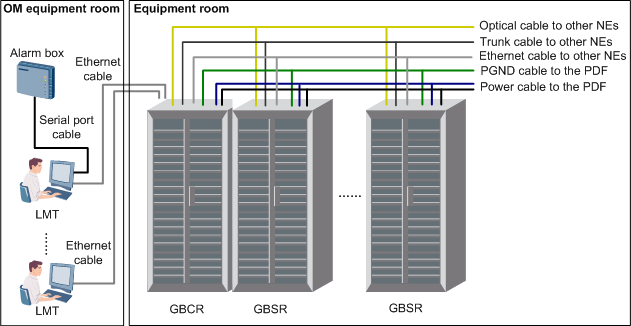
This describes the physical structure of the BSC, including the cabinet, cables, LMT computers, and alarm box.
Figure 1 shows the physical structure of the BSC.

| LMT: Local Maintenance Terminal | PDF: Power Distribution Frame |
Table 1 lists the components of the BSC.
Component |
Introduction |
Refer to... |
|---|---|---|
GSM BSC control processing rack (GBCR) |
The GBCR provides switching and processes services for the BSC. One GBCR is configured in a BSC. |
For details, refer to GBCR (Configuration Type A) and GBCR (Configuration Type B). |
GSM BSC service processing rack (GBSR) |
The GBSR processes various services for the BSC. The number of GBSRs to be configured depends on the traffic volume. Zero to three GBSRs can be configured. |
|
BSC Cables |
BSC cables are classified into the Ethernet cables, optical cables, and E1/T1 cables. The number of BSC cables to be configured depends on actual requirements. |
|
BSC LMT |
The LMT is a computer that is installed with the LMT software package and is connected to the OM network of the NEs. It is optional for the BSC. |
|
Alarm box |
The alarm box can generate audible and visual alarms. It is optional for the BSC. |
User manual delivered with the alarm box |