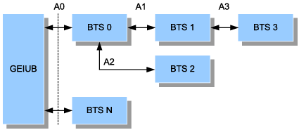
This provides examples of timeslot assignment on the Abis interface in the tree topology.
The timeslot assignment in each multiplexing mode is based on the following conditions:
- The speech rate is 16 kbit/s. Four channels of speech occupy one 64 kbit/s timeslot on the Abis interface.
- For the first TRX, channel 0 (T00C0) is the BCCH and channel 1 (T00C1) is the SDCCH.
- The BCCH and SDCCH use RSLs, that is, the timeslots occupied by T00C0 and T00C1 are included in the timeslots occupied by RSLs. Therefore, T00C0 and T00C1 are not listed in the following tables.
Figure 1 shows the tree topology.
The multiplexing modes of BTS 0, BTS 1, BTS 2, and BTS 3 are 1:1, 2:1, 3:1, and 4:1 respectively. Each BTS is configured with a cell, the cell is configured with two TRXs, and the channels in the cell use default settings.
BTS 0 is the parent node. Table 1-Table 4 shows the timeslot assignment on E1s (A0-A3) of BTSs.
Timeslot No. |
Sub Timeslot No. |
|||
|---|---|---|---|---|
0, 1 |
2, 3 |
4, 5 |
6, 7 |
|
0 |
Synchronization |
Synchronization |
Synchronization |
Synchronization |
1 |
RSL00 |
|||
2 |
T00C2 |
T00C3 |
T00C4 |
T00C5 |
3 |
T00C6 |
T00C7 |
T01C0 |
T01C1 |
4 |
RSL01 |
|||
5 |
T01C2 |
T01C3 |
T01C4 |
T01C5 |
6 |
T01C6 |
T01C7 |
||
7 |
OML1 + RSL10 |
|||
8 |
T10C2 |
T10C3 |
T10C4 |
T10C5 |
9 |
T10C6 |
T10C7 |
T11C0 |
T11C1 |
10 |
RSL11 |
|||
11 |
T11C2 |
T11C3 |
T11C4 |
T11C5 |
12 |
T11C06 |
T11C7 |
||
13 |
OML2+RSL20+RSL21 |
|||
14 |
T20C2 |
T20C3 |
T20C4 |
T20C5 |
15 |
T20C6 |
T20C7 |
T21C0 |
T21C1 |
16 |
T21C2 |
T21C3 |
T21C4 |
T21C5 |
17 |
T21C6 |
T21C7 |
||
18 |
OML3+ RSL30+RSL31 |
|||
19 |
T30C2 |
T30C3 |
T30C4 |
T30C5 |
20 |
T30C6 |
T30C7 |
T31C0 |
T31C1 |
21 |
T31C2 |
T31C3 |
T31C4 |
T31C5 |
22 |
T31C6 |
T31C7 |
||
23 |
||||
... |
||||
31 |
OML0 |
|||
Timeslot No. |
Sub Timeslot No. |
|||
|---|---|---|---|---|
0, 1 |
2, 3 |
4, 5 |
6, 7 |
|
0 |
Synchronization |
Synchronization |
Synchronization |
Synchronization |
1 |
T10C2 |
T10C3 |
T10C4 |
T10C5 |
2 |
T10C6 |
T10C7 |
T11C0 |
T11C1 |
3 |
RSL11 |
|||
4 |
T11C2 |
T11C3 |
T11C4 |
T11C5 |
5 |
T11C6 |
T11C7 |
||
6 |
OML3 + RSL30 + RSL31 |
|||
7 |
T30C2 |
T30C3 |
T30C4 |
T30C5 |
8 |
T30C6 |
T30C7 |
T31C0 |
T31C1 |
9 |
T31C2 |
T31C3 |
T31C4 |
T31C5 |
10 |
T31C06 |
T31C7 |
||
11 |
||||
... |
||||
31 |
OML1+ RSL10 |
|||
