This describes how to add a GFGUG in the GMPS/GEPS and configure its attributes. The GFGUG implements the IP transmission on the Gb interface for the BSC.
| Scenario | BSC initial configuration and BSC capacity expansion |
| Mandatory/Optional | Optional. The GFGUG is configured when the Gb over IP mode is adopted. |
Prerequisites
- The built-in PCU is configured.
- The subrack has an idle slot to hold the GFGUG.
When the GFGUG is used to implement the Gb over IP mode, the device IP address and the port IP address must be configured. The device IP address and the port IP address can implement end-to-end communication separately.
You can choose the port IP address or device IP address for communication on the Software Parameter tab page of BSC Attributes.
When the BSC is configured with two GFGUGs, you can set Net Mode to Inter-Board Active/Standby or Inter-Board load sharing to improve networking reliability. When the BSC is configured with only one GFGUG (Independent mode), you can configure routes to guarantee networking reliability.
In active/standby mode, the IP addresses of related ports must be configured on the same network segment. In load sharing mode, if the BSC performs communication through device IP addresses, then the two boards for load sharing must use the same device IP address. Regardless of whether device IP addresses or port IP addresses are used for communication, port IP addresses must be on different network segments.
Besides the configuration of the networking mode, you can configure BFD link detection and ARP link detection to improve system reliability. You can either ARP link detection or BFD link detection on one port. ARP link detection is available when NEs at one end of the ARP link support the ARP link detection. BFD link detection, however, is available only when NEs at both ends of the BFD link support the BFD link detection.
Preparation
The following procedure takes how to configure a GFGUG in the GMPS as an example.
Parameter |
Example |
Source |
|
|---|---|---|---|
Subrack No. |
0 |
BSC internal planning |
|
Slot No. |
18 |
BSC internal planning |
|
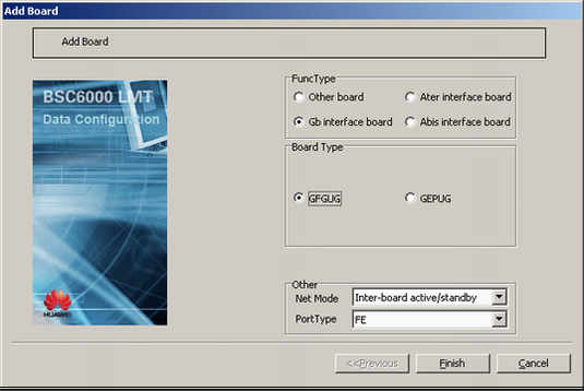
FuncType |
Gb interface board |
BSC internal planning |
|
Board Type |
GFGUG |
BSC internal planning |
|
Net Mode |
Inter-Board Active/Standby |
BSC internal planning |
|
Port Type |
FE |
BSC internal planning |
|
Load Key |
Server |
BSC internal planning |
|
Device IP address |
IP Address |
172.16.125.4 |
Negotiation with the peer end |
Subnet Mask |
255.255.255.0 |
Negotiation with the peer end |
|
Port IP address |
Port No. |
0 |
Negotiation with the peer end |
IP Address Index |
0 |
Negotiation with the peer end |
|
Ip Address |
172.16.5.4 |
Negotiation with the peer end |
|
Standby Ip Address |
172.16.5.44 |
Negotiation with the peer end |
|
Subnet Mask |
255.255.255.0 |
Negotiation with the peer end |
|
BSC route |
Destination IP Address |
172.16.124.25 |
Negotiation with the peer end |
Subnet Mask |
255.255.255.0 |
Negotiation with the peer end |
|
Gateway IP Address |
172.16.5.1 |
Negotiation with the peer end |
|
BFD Detect |
Port No. |
0 |
BSC internal planning |
IP Address Index |
0 |
Negotiation with the peer end |
|
Peer IP |
172.16.5.6 |
Negotiation with the peer end |
|
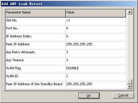
ARP link detection |
Port No. |
0 |
BSC internal planning |
IP Address Index |
0 |
Negotiation with the peer end |
|
Peer IP Address |
172.16.5.8 |
Negotiation with the peer end |
|
Procedure
- Add a board.
- Right-click an idle slot among slots 18-27 holding the GMPS, and then choose Add Board from the shortcut menu. A dialog box is displayed, as shown in Figure 1.
- Configure the board attributes.
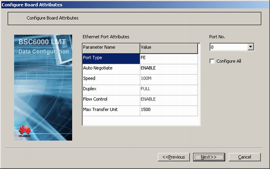
- Right-click GFGUG, and then choose from the shortcut menu. A dialog box is displayed, as shown in Figure 2.
- Set Load Key by referring to Table 1, and then click Next. A dialog box is displayed, as shown in Figure 3.
- Set the attributes of the Ethernet port by referring to Table 1.
 NOTE:
NOTE: When you modify the attributes of a port on the GFGUG, the port becomes faulty temporarily. If the board is in active/standby mode, an active/standby switchover is performed automatically.
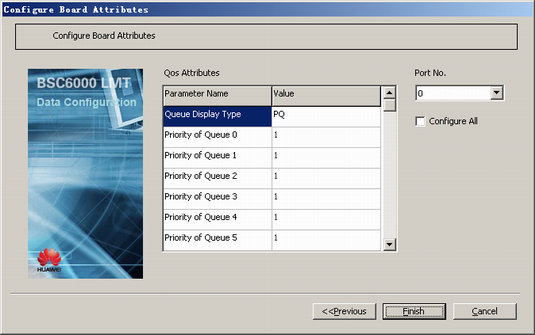
- Click Next. A dialog box is displayed, as shown in Figure 4.
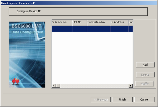
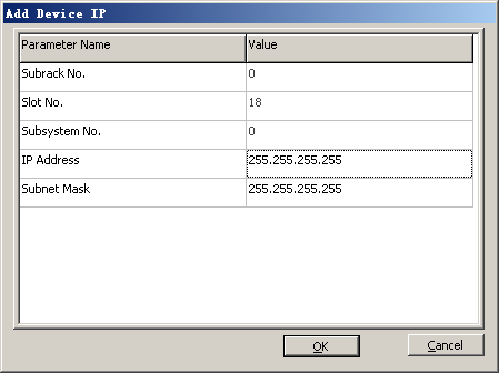
- Configure the device IP address.
- Right-click GFGUG, and then choose from the shortcut menu. A dialog box is displayed, as shown in Figure 5.
- Click Add. A dialog box is displayed, as shown in Figure 6.
- Set the parameters by referring to Table 1. Click OK to return to the dialog box, as shown in Figure 5. NOTE:
A device IP address is the IP address for implementing communication. This IP address is valid for the IP addresses of all the ports of the board. The device IP addresses for the interface boards operating in active/standby mode are the same. The IP addresses for the interface boards not operating in active/standby mode should not be arranged on the same network segment.
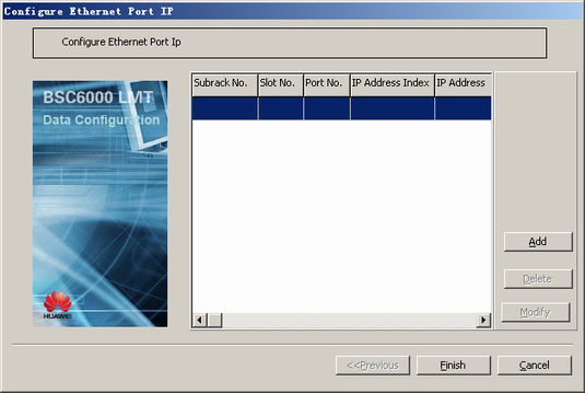
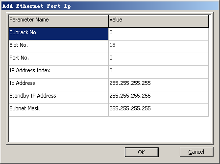
- Configure the port IP address.
- Right-click GFGUG, and then choose from the shortcut menu. A dialog box is displayed, as shown in Figure 7.
- Click Add. A dialog box is displayed, as shown in Figure 8.
- Set the parameters by referring to Table 1. Click OK to return to the dialog box, as shown in Figure 7. NOTE:
- One Ethernet port supports multiple IP addresses. That is, one Port No. can be configured with multiple Ip Address. The IP addresses of different IP Address Index for the same port must be located on different network segments. In addition, these network segments cannot have common parts.
- IP Address Index of a port is calculated automatically and not user-defined.
- For multiple IP addresses over one port, you must delete IP addresses with caution and cannot delete IP addresses in use.
- If Port Type is set to FE, one board can be configured with eight port IP addresses on different network segments. If Port Type is set to GE, one board can be configured with two port IP addresses on different network segments.
- The port IP address and the device IP address must be configured on different network segments. The port IP addresses for the active and standby GFGUGs must be configured on the same network segment.
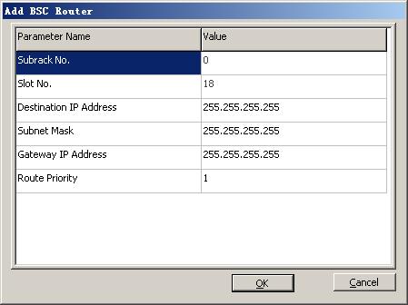
- Configure the BSC route.
- Right-click GFGUG, and then choose from the shortcut menu. A dialog box is displayed, as shown in Figure 9.
- Click Add. A dialog box is displayed, as shown in Figure 10.
- Set the parameters by referring to Table 1.
 CAUTION:
 Destination IP Address must be set to the network address, and it cannot be configured on the same network segment as the port IP address of the GFGUG. Otherwise, Destination IP Address is invalid.
Gateway IP Address and the port IP address of the GFGUG must be configured on the same network segment.
- Optional: Configure port link detection.
- Configure the BFD detection.
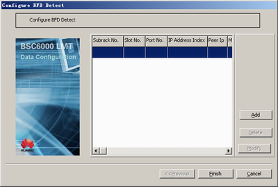
- Right-click GFGUG, and then choose from the shortcut menu. A dialog box is displayed, as shown in Figure 11.
NOTE:
- BFD detection and ARP link detection cannot be enabled at the same time.
- One port can be configured with only one detection mode. When a port is not configured with BFD detection or ARP link detection, physical layer detection is performed.
- Currently, you can configure detection modes in the following ways: BFD detection for both the active and standby ports, ARP link detection for both the active and standby ports, BFD detection for the active port and physical layer detection for the standby port, ARP link detection for the active port and physical layer detection for the standby port, and physical layer detection for both the active and standby ports.
- When configuring BFD link detection, you cannot configure the local description character, which is set to 1 by default.
- Click Add. A dialog box is displayed, as shown in Figure 12.
- Set the parameters by referring to Table 1. NOTE:
- The selected Port No. must be configured with the port IP address.
- Peer Ip must be different from the device IP address and the port IP address, and must be on the same network segment as the port IP address.
- In active/standby mode, Peer IP Address of the Standby Board can be configured and must be located on the same network segment as the corresponding port IP address. Peer IP Address of the Standby Board must be different from the device IP address and the port IP address but can be the same as Peer IP.
- In independent mode and load sharing mode, Peer IP Address of the Standby Board cannot be configured.
- Click OK to return to the dialog box, as shown in Figure 11.
- Click Finish. The configuration of the BFD detection is complete.
- Right-click GFGUG, and then choose from the shortcut menu. A dialog box is displayed, as shown in Figure 11.
- Configure ARP link detection.
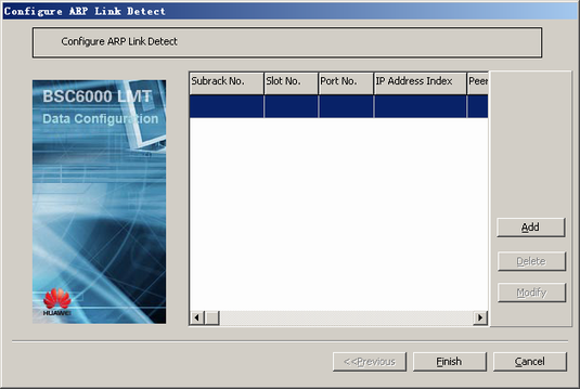
- Right-click GFGUG, and then choose from the shortcut menu. A dialog box is displayed, as shown in Figure 13.
- Click Add. A dialog box is displayed, as shown in Figure 14.
- Set the parameters by referring to Table 1. NOTE:
- One port can be configured with only one ARP/BFD detection.
- The selected port and IP address index must be configured with a port IP address.
- Peer IP Address must be different from the device IP address and the port IP address that are configured on the BSC.
- Peer IP Address must be located on the same network segment as the selected Port No. and IP Address Index.
- In active/standby mode, Peer IP Address of the Standby Board can be configured and must be located on the same network segment as the corresponding port IP address. Peer IP Address of the Standby Board must be different from the device IP address and the port IP address but can be the same as Peer IP Address.
- In independent mode and load sharing mode, Peer IP Address of the Standby Board cannot be configured.
- Click OK to return to the dialog box, as shown in Figure 13.
- Click Finish. The configuration of the ARP link detection is complete.
- Configure the BFD detection.