This describes how to add a GEIUB or GOIUB in the GMPS or GEPS and configure its attributes. The GEIUB and GOIUB are responsible for the E1/T1 transmission and STM-1 transmission on the Abis interface respectively.
| Scenario | BSC initial configuration and BSC capacity expansion |
| Mandatory/Optional | Mandatory |
Prerequisite
The subrack has idle slots to hold the GEIUB and GOIUB.
Preparation
Parameter |
Example |
Source |
|---|---|---|
Board Type |
GEIUB |
BSC internal planning |
Work Mode |
E1 |
BSC internal planning |
Active/Standby Mode |
Selected |
BSC internal planning |
Load Key |
Server |
BSC internal planning |
Parameter |
Example |
Source |
|---|---|---|
Board Type |
GOIUB |
BSC internal planning |
Work Mode |
E1 |
BSC internal planning |
Active/Standby Mode |
Selected |
BSC internal planning |
Load Key |
Server |
BSC internal planning |
Tributary Numbering |
HuaWei mode |
Negotiation with the peer |
TX J0 Byte |
MGW SDH DEFAULT (character string) |
Negotiation with the peer |
Expect RX J0 Byte |
MGW SDH DEFAULT (character string) |
Negotiation with the peer |
TX J1 Byte |
MGW SDH DEFAULT (character string) |
Negotiation with the peer |
Expect RX J1 Byte |
MGW SDH DEFAULT (character string) |
Negotiation with the peer |
TX J2 Byte |
MGW SDH DEFAULT (character string) |
Negotiation with the peer |
Expect RX J2 Byte |
MGW SDH DEFAULT (character string) |
Negotiation with the peer |
TX Frame Format |
CRC4_MULTIFRAME |
Negotiation with the peer |
RX Frame Format |
CRC4_MULTIFRAME |
Negotiation with the peer |
When the parameter Optical Interface Standard is set to SONET, you must configure the following parameters: High Order Path 1 TX J1 Byte, High Order Path 1 Expect RX J1 Byte, High Order Path 2 TX J1 Byte, High Order Path 2 Expect RX J1 Byte, High Order Path 3 TX J1 Byte, and High Order Path 3 Expect RX J1 Byte.
The procedures for configuring the GEIUB and GOIUB are the same. The following procedure takes how to add a pair of active/standby GEIUBs in the GMPS as an example.
Procedure
- On the BSC6000 Local Maintenance Terminal, click the BSC Device Panel tab. Select a cabinet number from the Current Cabinet drop-down list.
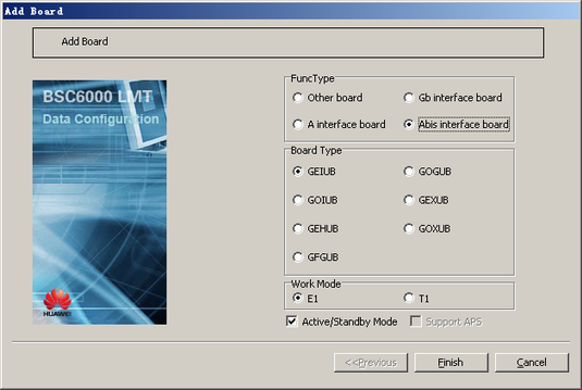
- Right-click an idle slot among slots 18-27 holding the GMPS, and then choose from the shortcut menu. A dialog box is displayed, as shown in Figure 1.
- Set Board Type to GEIUB and set other parameters by referring to Table 1.
- Click Finish. The addition of the GEIUB is complete.
- Right-click GEIUB, and then choose from the shortcut menu. A dialog box is displayed, as shown in Figure 2.
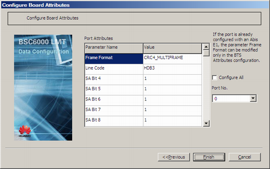
- Set Load Key, and then click Next. A dialog box is displayed, as shown in Figure 3.
 NOTE:
NOTE: - When configuring the attributes of the GEIUB port, you need to select the port number first.
- If you select Configure All, all the ports will be configured on the basis of the settings of the current ports displayed in the Port No. drop-down list.
- For the parameters in the dialog box shown in Figure 3, you can use the default settings or change them as required.
- Click Finish. The configuration of the GEIUB is complete.