This describes how to add modules other than RF modules for the DBS3900, BTS3900, and BTS3900A, including the APMU, DTCU, FMUA, FMU, DEMU, and GATM.
| Scenario | Adding BTS3900, BTS3900A, or DBS3900 outdoor base station. |
| Mandatory/Optional | Mandatory |
| NEs Involved | BTS3900 GSM, BTS3900 GSM/UMTS, BTS3900A GSM, BTS3900A GSM/UMTS, DBS3900 GSM (outdoor), DBS3900 GSM/UMTS (outdoor) |
Preparation
Table 1 lists the mandatory module types to be added and mandatory slot numbers to be configured for BTSs of different types. Table 2 lists the optional module types to be added and optional slot numbers to be configured for BTSs of different types.
Site Type |
Module Type |
Available Slot Number |
Mapping Physical Module |
|---|---|---|---|
DBS3900 GSM (outdoor) |
APMU |
2, 3 |
PMU module and APMI/HPMI |
DTCU |
6, 7, 18, 19 |
AFMU/HEUA |
|
DBS3900 GSM/UMTS (outdoor) |
APMU |
3 |
PMU module and APMI/HPMI |
DTCU |
7 |
AFMU/HEUA |
|
BTS3900 GSM BTS3900 GSM/UMTS |
FMU |
8-11 |
Fan board |
BTS3900A GSM |
APMU |
2, 3 |
PMU module and APMI/HPMI |
DTCU |
6, 7, 18, 19 |
AFMU/HEUA |
|
FMUA |
8-11 |
FMUA |
|
BTS3900A GSM/UMTS |
APMU |
3 |
PMU module and APMI/HPMI |
DTCU |
7 |
AFMU/HEUA |
|
FMUA |
8-11 |
FMUA |
Site Type |
Module Type |
Available Slot Number |
Configuration Conditions |
Mapping Physical Module |
|---|---|---|---|---|
DBS3900 GSM (indoor) DBS3900 GSM/UMTS (indoor) DBS3900 GSM (outdoor) DBS3900 GSM/UMTS (outdoor) BTS3900 GSM BTS3900 GSM/UMTS BTS3900A GSM BTS3900A GSM/UMTS |
DEMU |
0, 1 |
When the Boolean values provided by the existing UPEU and UEIU cannot meet the requirements of the telecom equipment room, you need to add the DEMU. |
EMUA |
GATM |
16, 17 |
|
GATM |
On a GSM/UMTS site, the RET antenna and TMA can be monitored on the UMTS side. When a GSM site is upgraded to a GSM/UMTS site, the RET antenna and TMA of the previous GSM site are still monitored by the GATM. That is, on the LMT, you do not need to delete the configuration of the GATM.
Procedure
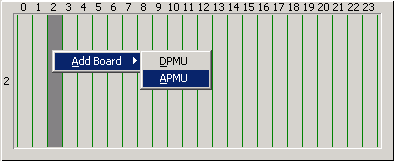
- Add the APMU.
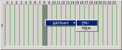
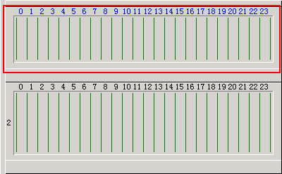
- In subrack 2 in the "Site Device Attributes" dialog box, right-click the corresponding slot as described in Table 1. A shortcut menu is displayed, as shown in Figure 2.
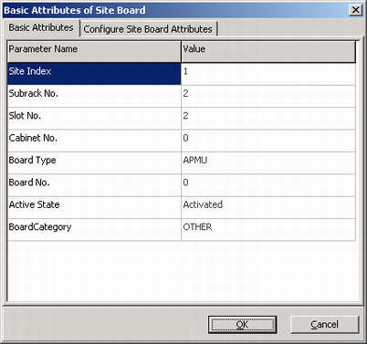
- Right-click the added APMU, and then choose Configure Board Attributes from the shortcut menu. A dialog box is displayed, as shown in Figure 3.
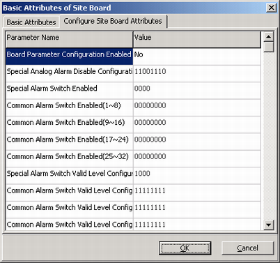
- Click the Configure Site Board Attributes tab to display the tab page, as shown in Figure 4.
- Set Board Parameter Configuration Enabled to Yes and configure parameters listed in Table 3. If a battery cabinet is configured, set Battery Cabinet Configuration Enabled to Yes.
Table 3 APMU parameters to be configured Board Parameter Configuration
Battery Cabinet Configuration
- APMU Board Application Scenario
- DPSU 0
- DPSU 1
- DPSU 2
- Battery Type
- Charge Coefficient
- Battery Capacity
 CAUTION:
 The parameters related to the battery cabinet must be configured in accordance with the actual situation. Otherwise, the battery cabinet cannot work properly.
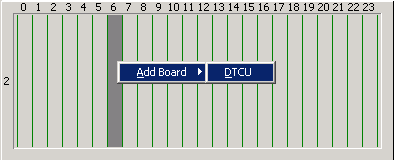
- Add the DTCU.
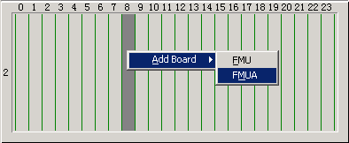
- Add the FMUA.
- Add the FMU.
- Add the GATM.
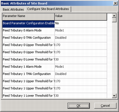
- Click the Configure Site Board Attributes tab to display the tab page, as shown in Figure 8.
- Set Board Parameter Configuration Enabled to Yes and configure parameters listed in Table 4.
Table 4 GATM parameters to be configured Parameter
Configuration Description
Feed Tributary 0 Alarm Mode
Set this parameter to Mode1, Mode2, or Mode3.
Mode 1: In this mode, there is only one alarm severity. The current for alarming is constant and higher than the normal operating current.
Mode 2: In this mode, there are two alarm severities: warning alarm and critical alarm. The current for alarming is constant and higher than the normal operating current.
Mode 3: In this mode, there are two alarm severalties: warning alarm and critical alarm. The current for reporting a warning alarm is a periodic pulse. The current for reporting a critical alarm is a constant current.
Feed Tributary 0 TMA Configuration
Set this parameter to Disabled or Enabled.
Feed Tributary 0 Upper Threshold for TMA Current Critical Alarm
The value range of this parameter is [0, 2000]. The default value is 170.
Feed Tributary 0 Upper Threshold for TMA Current Warning
The value range of this parameter is [0, 2000]. The default value is 170.
Feed Tributary 0 Lower Threshold for TMA Current Alarm
The value range of this parameter is [0, 2000]. The default value is 30.
 NOTE:
NOTE: The configurations of Feed Tributary 1 through 5 is the same as that of Feed Tributary 0 described in Table 4.
- Add the DEMU.
- Click the Configure Site Board Attributes tab to display the tab page, as shown in Figure 9.