This describes how to set antenna attributes, including the antenna TX/RX mode and TMA. If the BTS is configured with the GATM and RET antenna, you also need to set the attributes of the RET antenna.
| Mandatory/Optional | Mandatory |
| NEs Involved | DBS3900 GSM, DBS3900 GSM/UMTS, BTS3900 GSM, BTS3900 GSM/UMTS, BTS3900A GSM, BTS3900A GSM/UMTS |
Preparation
You can determine the send receive mode of the antenna in the following ways:
- Considering the number of antennas and connection modes of feeders
- Considering the receive mode and transmit mode of TRXs
The RRU3004 is a remote RF unit of the DBS3900. Each RF subrack has two RRU3004s. RRU3008 is the remote outdoor RF module. A single RRU3008 can support a maximum of eight TRXs. On the LMT, the RRU3004 should be configured as DRRU, the RRU3008 should be configured as GRRU.
Procedure
- In the left navigation tree on the BSC6000 Local Maintenance Terminal, right-click the corresponding BTS and then choose Configure Site Board Attributes from the shortcut menu.
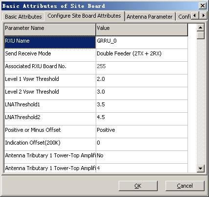
- In the displayed dialog box, click the Configure Site Board Attributes tab. The Site Device Attributes is displayed. Then, right-click the corresponding RF module and choose Configure RXU Attribute. In the Basic Attributes of Site Board dialog box, click the Configure Site Board Attributes tab, as shown in Figure 1.
- Set Send Receive Mode, namely the connection mode between the RF module and the antenna, based on the number of antennas, connection mode of feeders, and TRX receive and transmit modes. The principles to be followed are
described in Table 1.
Table 1 Principles during the setting of board attributes SN
Principles
1
When Send Receive Mode is set to Double Feeder (2TX + 4RX), you must configure Associated DRRU Board No. or Associated RXU Board No., which cannot be the number of the RF module itself or an RF module that already has an association with another module.
2
When two TRXs are bound in the DRRU and Send Receive Mode is set to Single Feeder (1TX + 1RX), Power Type can only be set to 15W.
3
When Send Receive Mode is set to Single Feeder (2TX + 4RX) for the GRFU or MRFU, Associated RXU Board No. can be configured only when Support Diversity Transmitter or Four Diversity Receiver is set to Yes.
4
When the transmit mode of the TRX is diversity transmitter, Send Receive Mode must be set to Double Feeder (2TX + 2RX) or Double Feeder (2TX + 4RX).
5
When the receive mode of the TRX is four diversity receiver, Send Receive Mode must be set to Double Feeder (2TX + 4RX).
6
When Send Receive Mode of the DRRU is set to Double Feeder (2TX + 2RX) or Double Feeder (2TX + 4RX), the power of the TRX must be set to a 40W or 45W.
7
If the RX/TX mode of the DRFU is set to Single Feeder (1TX + 1RX), Single Feeder (1TX + 2RX), Double Feeder (1TX + 1RX), or Double Feeder (1TX + 2RX), and the DRFU is bound to two TRXs, the power of the TRX should not be set to a 40W or 45W.
- Configure the TMA and the tower-top amplifier attenuation factor. For details, see Table 2. The BTS adjusts the gain for the board depending on the configurations of the TMA and the tower-top amplifier attenuation factor.
- Click OK to return to the Site Device Attributes dialog box.
If...
Then...
The BTS is configured with the GATM and RET antenna,
Perform 6.
The BTS is not configured with the RET antenna or is configured with the RET antenna but not the GATM,
End the operation to finish the setting of the antenna attributes.
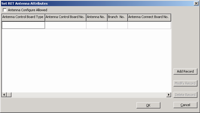
- In the Site Device Attributes dialog box, click Set RET Antenna Attributes. A dialog box is displayed, as shown in Figure 2.
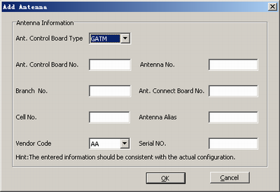
- Click Add Record. A dialog box is displayed, as shown in Figure 3. Then, set related parameters according to Table 3.
Table 3 Configuration of RET antenna parameters Parameter
Description of the Configuration
Ant. Control Board No.
Set the parameters according to the actual situation. The RET antenna may not work properly if errors exist in the settings.
Branch No.
Ant. Connect Board No.
Cell No.
Antenna No.
The value range is [0,35].
When multiple RET antennas are added, Antenna No. of different RET antennas must be different.
Antenna Alias
Principle: The antenna alias should be easy to identify.
Vendor Code
Obtain the values of the parameters from the label of the actual RET control unit (RCU).
Serial No.
- Click OK to return to the Set RET Antenna Attributes dialog box.
- Select Antenna Configure Allowed, and then click Yes to return to the Site Device Attributes dialog box. The setting of antenna attributes is complete.