This describes how to configure the DFCU and its antenna feeder attributes for the BTS3012, BTS3012 II, or BTS3012AE to achieve the four-in-one output of TRXs.
| Scenario | BSC initial configuration |
| Mandatory/Optional | Optional. Only one DFCU is configured when the four-in-one output of TRXs needs to be implemented in the BTS3012, BTS3012 II, or BTS3012AE. |
- The DFCU can independently provide the four-in-one output of TRXs.
- The DFCU cannot be bound to the QTRU.
- The DFCU should not be configured in slot 20 of the DAFU subrack in the BTS3012, BTS3012 II, or BTS3012AE. The slots on both sides of the DFCU slot should not be configured with the DFCU or the DFCB.
- The TRX to be tuned must be configured on downlink tributary A of the DFCU. Tributary B should not be configured with TRXs.
- The frequency band type of the DFCU must be the same as that of the TRX in the BTS.
Prerequisite
The frequency band type of the TRX in the BTS is specified.
Preparation
Parameter |
Example |
Source |
|
|---|---|---|---|
Antenna feeder attributes |
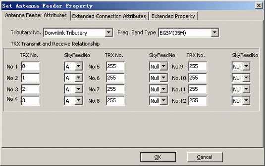
Tributary No. |
Downlink Tributary |
Network planning |
Frequency Band |
EGSM(35M) |
Network planning |
|
TRX Transmit and Receive Relationship |
TRX No.1: 0, A TRX No.2: 1, A TRX No.3: 2, A TRX No.4: 3, A |
Network planning |
|
Procedure
- On the BSC6000 Local Maintenance Terminal, right-click the BTS.
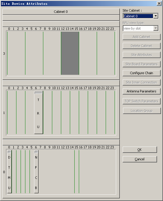
- Choose . A dialog box is displayed, as shown in Figure 1.
- Click Add or Delete Board. A dialog box is displayed, as shown in Figure 2.
- Right-click an empty slot, and then choose from the shortcut menu. A DFCU is added.
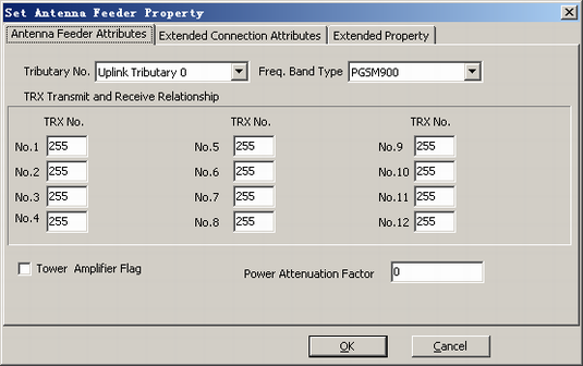
- Right-click DFCU, and then choose from the shortcut menu. A dialog box is displayed, as shown in Figure 3.
- For details, see Table 1 to set the parameters, as shown in Figure 4.
- Click OK to return to the dialog box shown in Figure 2.
- Click OK to return to the dialog box shown in Figure 1.
- Click Finish. The configuration of the antenna feeder attributes of the DFCU is complete.