This describes how to configure two DFCUs and one DFCB for the BTS3012, BTS3012 II, or BTS3012AE to achieve the TRX combination output for the S12 cell.
| Scenario | BSC initial configuration |
| Mandatory/Optional | Optional. Two DFCUs and one DFCB are configured when the TRX combination output for the S12 cell needs to be implemented in the BTS3012, BTS3012 II, or BTS3012AE. |
Prerequisite
The frequency band type of the TRX in the BTS is specified.
Preparation
Parameter |
Example |
Source |
|
|---|---|---|---|
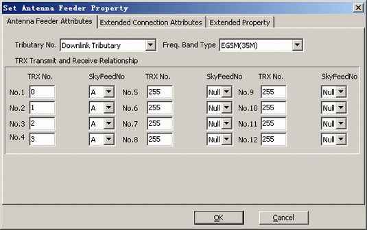
Antenna feeder attributes of DFCU 0 |
Tributary No. |
Downlink Tributary |
Network planning |
Freq. Band Type |
EGSM(35M) |
Network planning |
|
TRX Transmit and Receive Relationship |
TRX No.1: 0, A TRX No.2: 1, A TRX No.3: 2, A TRX No.4: 3, A |
Network planning |
|
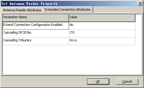
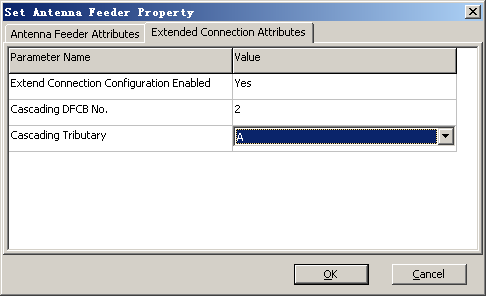
Extension connection attributes of DFCU 0 |
Extend Connection Configuration Enabled |
Yes |
Network planning |
Cascading DFCB No. |
2 |
Network planning |
|
Cascading Tributary |
A |
Network planning |
|
Antenna feeder attributes of DFCU 1 |
Tributary No. |
Downlink Tributary |
Network planning |
Freq. Band Type |
EGSM(35M) |
Network planning |
|
TRX Transmit and Receive Relationship |
TRX No.1: 6, A TRX No.2: 7, A TRX No.3: 8, A TRX No.4: 9, A |
Network planning |
|
Extension connection attributes of the DFCU 1 |
Extend Connection Configuration Enabled |
Yes |
Network planning |
Cascading DFCB No. |
2 |
Network planning |
|
Cascading Tributary |
B |
Network planning |
|
Antenna feeder attributes of the DFCB |
Tributary No. |
Downlink Tributary |
Network planning |
Freq. Band Type |
EGSM(35M) |
Network planning |
|
TRX Transmit and Receive Relationship |
TRX No.1: 4, A TRX No.2: 5, A TRX No.1: 10, B TRX No.2: 11, B |
Network planning |
|
Procedure
- On the BSC6000 Local Maintenance Terminal, right-click the target BTS.
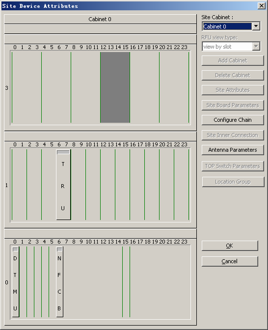
- Choose from the shortcut menu. A dialog box is displayed, as shown in Figure 1.
- Click Add or Delete Board. A dialog box is displayed, as shown in Figure 2.
- Right-click an idle slot and then choose from the shortcut menu. A DFCB is added.
- Right-click DFCB and choose from the shortcut menu. A dialog box is displayed, as shown in Figure 3.
- See Table 1 to set the parameters, as shown in Figure 4.
- Click OK to return to the dialog box shown in Figure 2.
- Right-click an idle slot.
- Choose from the shortcut menu. A DFCU is added.
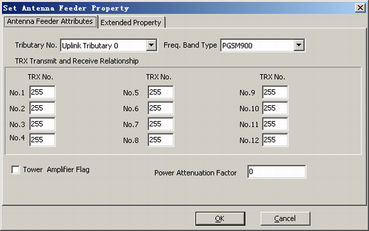
- Right-click DFCU and choose from the shortcut menu. A dialog box is displayed, as shown in Figure 5.
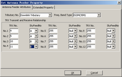
- See Table 1 to set the parameters, as shown in Figure 6.
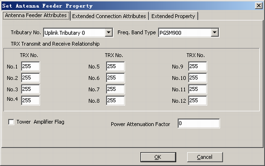
- Click the Extended Connection Attributes tab. The tab page is displayed, as shown in Figure 7.
- See Table 1 to set the parameters, as shown in Figure 8.
- Click OK. The configuration of the extension connection attributes of the DFCU is complete.
- Repeat 8 through 14 to configure DFCU 1.
 CAUTION:
 Cascading Tributary among the Extended Connection Attributes on the tab page of DFCU 1 should be set to B.