The bitmap has four basic header types:
The four types of bitmap headers are differentiated by the Size member, which is the first DWORD in each of the structures.
The BITMAPV5HEADER structure is an extended BITMAPV4HEADER structure, which is an extended BITMAPINFOHEADER structure. However, the BITMAPINFOHEADER and BITMAPCOREHEADER have only the Size member in common with other bitmap header structures.
The BITMAPCOREHEADER and BITMAPV4HEADER formats have been superceded by BITMAPINFOHEADER and BITMAPV5HEADER formats, respectively. The BITMAPCOREHEADER and BITMAPV4HEADER formats are presented for completeness and backward compatibility.
The BITMAPFILEHEADER structure contains information about the type, size, and layout of a file that contains a device-independent bitmap. A BITMAPINFO or BITMAPCOREINFO structure immediately follows the BITMAPFILEHEADER structure in the DIB file.
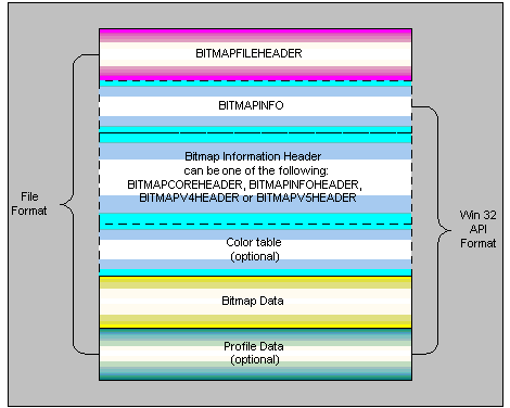
The file format is a description of how to read or store bitmap data in a file. The file format and the format used by Win32 API are similar but not identical. There are small differences between the two. The file format has a file header (BITMAPFILEHEADER), whereas the Win32 API format does not use this header. In the following illustration, all segments are used for file format, while the Win32 API format excludes BITMAPFILEHEADER.

A color table describes how pixel values correspond to RGB color values. RGB is a model for describing colors that are produced by emitting light.
Profile data refers to either the profile file name ( linked profile) or the actual profile bits (embedded profile). When the file format contains profile data, it should be placed at the end of the file. The Win32 API format places profile data just after the color table (if present). The exception to the Win32 API format is for those Win32 functions that receive a packed DIB, where the profile data comes after the bitmap bits, like the file format.
Profile data will only exist for BITMAPV5HEADER structures where bV5CSType is PROFILE_LINKED or PROFILE_EMBEDDED. For Win32 functions that receive packed DIBs, the profile data comes after the bitmap data.
A palettized device is any device that uses palettes to assign colors. The classic example of a palettized device is a display running in 8 bit color depth (i.e. 256 colors). The display in this mode uses a small color table to assign colors to a bitmap. The colors in a bitmap are assigned to the closest color in the palette that the device is using. The palettized device does not create an optimal palette for displaying the bitmap; it simply uses what ever is in the current palette. Applications are responsible for creating a palette and selecting it in to the system. In general, 16, 24, and 32 bpp bitmaps do not contain color tables (a.k.a. optimal palettes for the bitmap); the application is responsible for generating a optimal palette in this case. However, 16, 24, and 32 bpp can contain such optimal color tables for displaying on palettized devices; in this case the application just needs to create a palette based off of the color table present in the bitmap file.
Bitmaps that are 1, 4, or 8 bits per pixel (bpp) must have a color table with a maximum size based on the bpp. The maximum size for 1, 4, and 8 bpp bitmaps is 2 to the power of the bpp. 1 bpp maximum size is 2. 4 bpp is 16 colors. 8 bpp is 256 colors.
Bitmaps that are 16, 24, or 32 bpp do not require color tables, but may have them to specify colors for palettized devices. If a color table is present for 16, 24 or 32 bpp bitmap the ClrUsed field will specify the size of the color table and the color table must have that many colors in it. ClrUsed of zero indicates no color table.
The red, green and blue bit field masks for BI_BITFIELD bitmaps immediately follow the BITMAPINFOHEADER, BITMAPV4HEADER, and BITMAPV5HEADER structures. The BITMAPV4HEADER and BITMAPV5HEADER structures contain additional members for red, green and blue masks as follows:
| Member | Meaning |
|---|---|
| RedMask | Color mask that specifies the red component of each pixel, valid only if the Compression member is set to BI_BITFIELDS. |
| GreenMask | Color mask that specifies the green component of each pixel, valid only if the Compression member is set to BI_BITFIELDS. |
| BlueMask | Color mask that specifies the blue component of each pixel, valid only if the Compression member is set to BI_BITFIELDS. |
When the biCompression member of BITMAPINFOHEADER is set to BI_BITFIELDS and the function receives an argument of type LPBITMAPINFO, the color masks will immediately follow the header. The color table, if present, will follow the color masks. BITMAPCOREHEADER bitmaps do not support color masks.
By default, bitmap data is bottom-up in its format. Bottom-up means that the first scan line in the bitmap data is the last scan line to be displayed. For example, the 0th pixel of the 0th scan line of the bitmap data of a 10 pixel by 10 pixel bitmap will be the 0th pixel of the 9th scan line of the displayed or printed image. Run-length encoded (RLE) format bitmaps and BITMAPCOREHEADER bitmaps can not be top down bitmaps. The scan lines are DWORD aligned, except for RLE compressed bitmaps. They must be padded for scan line widths, in bytes, that are not evenly divisible by 4, except for RLE compressed bitmaps. For example, a 10 by 10 pixel 24 bpp bitmap will have 2 padding bytes at the end of each scan line.