A typical deployment of PPTP starts with a remote or mobile PPTP client that uses a local Internet Service Provider (ISP) to access a private enterprise LAN. This PPTP client can be running either Windows NT Server version 4.0, Windows NT Workstation version 4.0, or Windows 95 operating systems.
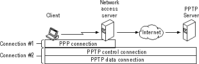
A PPTP client must make two connections to establish a PPTP tunnel. Figure 1 shows these connections. The client first uses Dial-Up Networking and the remote access protocol, PPP, to connect to a network access server (NAS) at an ISP facility. Once connected, the client can send and receive packets over the Internet. The network access server uses the TCP/IP protocol for all traffic to the Internet.
Note Network access servers are also referred to as front-end processors (FEPs), dial-in servers or point-of-presence (POP) servers.
The client then uses Dial-Up Networking to make a second logical connection over the existing PPP connection. Data sent using this second connection is in the form of IP datagrams that contain PPP packets, referred to as encapsulated PPP packets.
The second connection creates the virtual private networking (VPN) connection to a PPTP server on the private enterprise LAN (a computer running Windows NT Server version 4.0 and configured as a PPTP server). This connection is referred to as a tunnel.
Tunneling is the process of sending packets to a computer on a private network by routing them over some other network, such as the Internet. The other network’s routers cannot access computers on the private network. However, tunneling enables the routing network to transmit the packet to an intermediary computer, a PPTP server that is connected to the both the routing network and the private network. Both the PPTP client and the PPTP server use tunneling to securely route packets to a computer on the private network by using routers that only know the address of the private network intermediary server.
When the PPTP server receives the packet from the routing network, it sends it across the private network to the destination computer. The PPTP server does this by processing the PPTP packet to obtain the private network computer name or address information in the encapsulated PPP packet. Note that the encapsulated PPP packet can contain multi-protocol data such as IP, IPX, or NetBEUI protocols. Because the PPTP server is configured to communicate across the private network by using private network protocols, it is able to read multi-protocol packets.
The following figure illustrates the multi-protocol support built into PPTP. A packet sent from the PPTP client to the PPTP server passes through the PPTP tunnel to a destination computer on the private network.
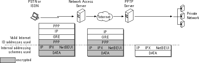
PPTP encapsulates the encrypted and compressed PPP packets into IP datagrams for transmission over the Internet. The IP datagrams are created using a modified version of the Internet Generic Routing Encapsulation (GRE) protocol. (GRE is defined in RFCs 1701 and 1702).These IP datagrams are routed over the Internet until they reach the PPTP server that is connected to both the Internet and the private network. The PPTP server disassembles the IP datagram into a PPP packet and then decrypts the PPP packet using the network protocol of the private network. As mentioned earlier, the network protocols on the private network that are supported by PPTP are IPX, NetBEUI, and TCP/IP.