Managing the Graphics State

Instructions can be used to set the value of Graphics State variables and, in some cases, to retrieve their current value.

Getting a value

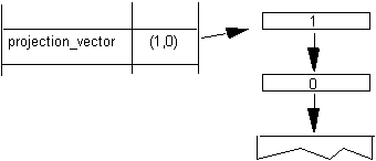
Instructions that retrieve the value of a state variable have names that begin with the word get. Get instructions will return the value of the state variable in question by placing that value on the top of the stack.

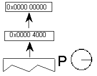
The illustration shows the effect of a GPV or get projection_vector instruction. It takes the x and y components of the projection_vector from the Graphics State and places them on the stack.

Setting a value

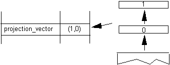
Instructions that change the value of a Graphics State variable have a name that begins with the word set. Set instructions expect their arguments to be at the top of the interpreter stack.

Figure 3–4 Setting the value of the Graphics State variable projection_vector
In addition to simple sets and gets, some instructions exist to simplify management of the values of state variables. For example, a number of instructions exist to set the direction of the freedom_vector and the projection_vector. In setting a vector, it is possible to set it to either of the coordinate axes, to the direction specified by a line, or to a direction specified by values taken from the stack. An instruction exists that directly sets the freedom_vector to the same value as the projection_vector.

Set freedom and projection Vectors To Coordinate Axis
SVTCA[a]

Code range

0x00 - 0x01

a

0: set vectors to the y-axis

1: set vectors to the x-axis

Pops

Pushes

Sets

projection_vector

freedom_vector


Sets both the projection_vector and freedom_vector to the same one of the coordinate axes.

The SVTCA is a shortcut for using both the SFVTCA and SPVTCA instructions. SVTCA[1] is equivalent to SFVTCA[1] followed by SPVTCA[1]. This instruction ensures that both movement and measurement are along the same coordinate axis.

Example:

SVTCA[1]

Sets both measurement and movement to the x-direction.

SVTCA[0]

Sets both measurement and movement to the y-direction.

Set Projection_Vector To Coordinate Axis
SPVTCA[a]

Code range

0x02 - 0x03

a

0: set the projection_vector to the y-axis

1: set the projection_vector to the x-axis

Pops

Pushes

Sets

projection_vector


Sets the projection_vector to one of the coordinate axes depending on the value of the flag a.

Example:

SPVTCA[0]

Sets the projection_vector to the y-axis assuring the measurement will be in that direction.

Set Freedom_Vector to Coordinate Axis
SFVTCA[a]

Code range

0x04 - 0x05

a

0: set the freedom_vector to the y-axis

1: set the freedom_vector to the x-axis

Pops

Pushes

Sets

freedom_vector


Sets the freedom_vector to one of the coordinate axes depending upon the value of the flag a.

Example:

SFVTCA[0]

Sets the freedom_vector to the y-axis ensuring that movement will be along that axis.

Set Projection_Vector To Line
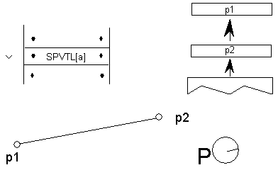
SPVTL[a]

Code Range

0x06 - 0x07

a

0: sets projection_vector to be parallel to line segment from p1 to p2

1: sets projection_vector to be perpendicular to line segment from p1 to
p2; the vector is rotated counter clockwise 90 degrees

Pops

p1: point number (ULONG)

p2: point number (ULONG)

Pushes

Uses

point p1 in the zone pointed at by zp2

point p2 in the zone pointed at by zp1

Sets

projection_vector


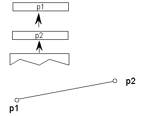
Sets the projection_vector to a unit vector parallel or perpendicular to the line segment from point p1 to point p2.

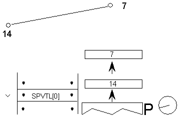
If parallel, the projection_vector points from p1 toward p2 as shown.

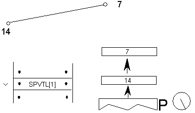
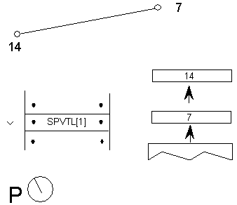
If perpendicular the projection_vector is obtained by rotating the parallel vector in a counter clockwise manner as shown.

case 1:

SPVTL[1]

Sets the projection_vector to be parallel to the line from point 7 to point 14.

case 2:

SPVTL[1]

Sets the projection_vector to be perpendicular to the line from point 7 to point 14.

case 3:

SPVTL[1]

The order in which the points are specified matters. This instruction sets the projection_vector to be perpendicular to the line from point 14 to point 7.

Set Freedom_Vector To Line
SFVTL[a]

Code Range

0x08 - 0x09

a

0: set freedom_vector to be parallel to the line segment defined by points p1 and p2

1: set freedom_vector perpendicular to the line segment defined by points p1 and p2; the vector is rotated counter clockwise 90 degrees

Pops

p1: point number (ULONG)

p2: point number (ULONG)

Pushes

Sets

freedom_vector

Uses

point p1 in the zone pointed at by zp2

point p2 in the zone pointed at by zp1


Sets the freedom_vector to a unit vector parallel or perpendicular to the line segment defined by points p1 and p2.

If parallel the freedom_vector points from p1 toward p2 as shown.

If perpendicular the freedom_vector is obtained by rotating the parallel vector in a counter clockwise manner as shown.

Set Freedom_Vector To Projection Vector
SFVTPV[ ]

Code

0x0E

Pops

Pushes

Sets

freedom_vector


Sets the freedom_vector to be the same as the projection_vector.

Before

After

Set Dual Projection_Vector To Line
SDPVTL[a]

Code Range

0x86 - 0x87

a

0: Vectors are parallel to line

1: Vectors are perpendicular to line

Pops

p1: first point number (ULONG)

p2: second point number (ULONG)

Pushes

Sets

dual_projection_vector and projection_vector

Uses

point p1 in the zone pointed at by zp2

point p2 in the zone pointed at by zp1


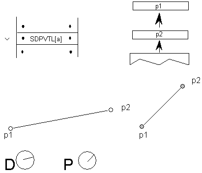
Pops two point numbers from the stack and uses them to specify a line that defines a second, dual_projection_vector. This dual_projection_vector uses coordinates from the scaled outline before any grid-fitting took place. It is used only with the IP, GC, MD, MDRP and MIRP instructions. Those instructions will use the dual_projection_vector when they measure distances between ungrid-fitted points. The dual_projection_vector will disappear when any other instruction that sets the projection_vector is used.

Note:

The dual_projection_vector is set parallel to the points as they appeared in the original outline before any grid-fitting took place.

Set Projection_Vector From Stack
SPVFS[ ]

Code Range

0x0A

Pops

y: y component of projection_vector (2.14 fixed point number padded with zeroes)

x: x component of projection_vector (2.14 fixed point number padded with zeroes)

Pushes

Sets

projection_vector


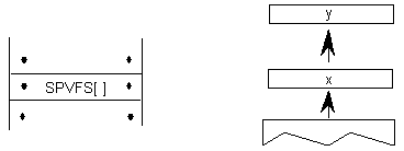
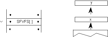
Sets the direction of the projection_vector, using values x and y taken from the stack, so that its projections onto the x and y-axes are x and y, which are specified as signed (two's complement) fixed-point (2.14) numbers. The square root of (x2 + y2) must be equal to 0x4000 (hex).

If values are to be saved and used by a glyph program, font program or preprogram across different resolutions, extreme care must be used. The values taken from or put on the stack are 2.14 fixed-point values for the x and y components of the vector in question. The values are based on the normalized vector lengths. More simply, the values must always be set such that (X**2 + Y**2) is 1.

If a TrueType program uses specific values for X and Y to set the vectors to certain angles, these values will not produce identical results across different aspect ratios. Values that work correctly at 1:1 aspect ratios (such as VGA and 8514) will not necessarily yield the desired results at a ratio of 1.33:1 (e.g. the EGA).

By the same token, if a TrueType program is making use of the values returned by GPV and GFV, the values returned for a specific angle will vary with the aspect ratio in use at the time.

Example:

SPVFS[ ]

Sets the projection_vector to a unit vector that points in the direction of the x-axis

Set Freedom_Vector From Stack

SFVFS[ ]

Code

0x0B

Pops

y: y component of freedom_vector (2.14 fixed point number padded with zeroes)

x: x component of freedom_vector (2.14 fixed point number padded with zeroes)

Pushes

Sets

freedom_vector


Sets the direction of the freedom_vector using the values x and y taken from the stack. The vector is set so that its projections onto the x and y -axes are x and y, which are specified as signed (two's complement) fixed-point (2.14) numbers. The square root of (x2 + y2) must be equal to 0x4000 (hex).

If values are to be saved and used by a glyph program, font program or preprogram across different resolutions, extreme care must be used. The values taken from or put on the stack are 2.14 fixed-point values for the x and y components of the vector in question. The values are based on the normalized vector lengths. More simply, the values must always be set such that (X**2 + Y**2) is 1.

If a TrueType program uses specific values for X and Y to set the vectors to certain angles, these values will not produce identical results across different aspect ratios. Values that work correctly at 1:1 aspect ratios (such as VGA and 8514) will not necessarily yield the desired results at a ratio of 1.33:1 (e.g. the EGA).

By the same token, if a TrueType program is making use of the values returned by GPV and GFV, the values returned for a specific angle will vary with the aspect ratio in use at the time.

Example:

Sets the freedom_vector to a unit vector that points in the direction of the y-axis.

Get Projection_Vector
GPV[ ]

Code Range

0x0C

Pops

Pushes

x: x component of projection_vector (2.14 fixed point number padded with zeroes)

y : y component of projection_vector (2.14 fixed point number padded with zeroes)

Gets

projection_vector


Pushes the x and y components of the projection_vector onto the stack as two 2.14 numbers.

If values are to be saved and used by a glyph program, font program or preprogram across different resolutions, extreme care must be used. The values taken from or put on the stack are 2.14 fixed-point values for the x and y components of the vector in question. The values are based on the normalized vector lengths. More simply, the values must always be set such that (X**2 + Y**2) is 1.

If a TrueType program uses specific values for X and Y to set the vectors to certain angles, these values will not produce identical results across different aspect ratios. Values that work correctly at 1:1 aspect ratios (such as VGA and 8514) will not necessarily yield the desired results at a ratio of 1.33:1 (e.g. the EGA).

By the same token, if a TrueType program is making use of the values returned by GPV and GFV, the values returned for a specific angle will vary with the aspect ratio in use at the time.

Example:

case 1:

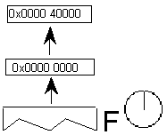
The stack entry 0x4000 which when interpreted as a 2.14 number is simply 1. This command reveals that, in this case, the projection_vector is a unit vector that points in the x-direction.

case 2:

Here the projection_vector is a unit vector that points in the direction of the y-axis.

case 3:

Note:

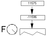
0x2D41 is the hex equivalent of . As a result of this instruction, the projection_vector is set to a 45 degree angle relative to the x-axis.

Get Freedom_Vector
GFV[ ]

Code Range

0x0D

Pops

Pushes

x: x-component of freedom_vector (2.14 number padded with zeroes)

y: y component of freedom_vector (2.14 number padded with zeroes)

Gets

freedom_vector


Puts the x and y components of the freedom_vector on the stack. The freedom_vector is put onto the stack as two 2.14 coordinates.

If values are to be saved and used by a glyph program, font program or preprogram across different resolutions, extreme care must be used. The values taken from or put on the stack are 2.14 fixed-point values for the x and y components of the vector in question. The values are based on the normalized vector lengths. More simply, the values must always be set such that (X**2 + Y**2) is 1.

If a TrueType program uses specific values for X and Y to set the vectors to certain angles, these values will not produce identical results across different aspect ratios. Values that work correctly at 1:1 aspect ratios (such as VGA and 8514) will not necessarily yield the desired results at a ratio of 1.33:1 (e.g. the EGA).

By the same token, if a TrueType program is making use of the values returned by GPV and GFV, the values returned for a specific angle will vary with the aspect ratio in use at the time.

Example

GFV[ ]

Set Reference Point 0
SRP0[ ]

Code Range

0x10

Pops

p: point number (ULONG)

Pushes

Sets

rp0

Affects

IP, MDAP, MIAP, MIRP, MSIRP, SHC, SHE, SHP


Pops a point number from the stack and sets rp0 to that point number.

Set Reference Point 1
SRP1[ ]

Code Range

0x11

Pops

p: point number (ULONG)

Pushes

Sets

rp1

Affects

IP, MDAP, MDRP, MIAP, MSIRP, SHC, SHE, SHP


Pops a point number from the stack and sets rp1 to that point number.

Set Reference Point 2
SRP2[ ]

Code Range

0x12

Pops

p:point number (ULONG)

Pushes

Sets

rp2


Pops a point number from the stack and sets rp2 to that point number.

Set Zone Pointer 0
SZP0[ ]

Code Range

0x13

Pops

n: zone number (ULONG)

Pushes

Sets

zp0

Affects

ALIGNPTS, ALIGNRP, DELTAP1, DELTAP2, DELTAP3, IP, ISECT, MD, MDAP, MIAP, MIRP, MSIRP, SHC, SHE, SHP, UTP


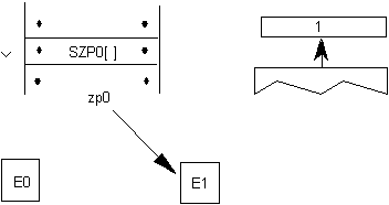
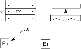
Pops a zone number, n, from the stack and sets zp0 to the zone with that number. If n is 0, zp0 points to zone 0. If n is 1, zp0 points to zone 1. Any other value for n is an error.

Example:

Set Zone Pointer 1
SZP1[ ]

Code Range

0x14

Pops

n: zone number (ULONG)

Pushes

Sets

zp1

Affects

ALIGNRPTS, ALIGNRP, IP, MD, MDRP, MSIRP, SHC, SHE, SHP, SFVTL, SPVTL


Pops a zone number, n, from the stack and sets zp1 to the zone with that number. If n is 0, zp1 points to zone 0. If n is 1, zp1 points to zone 1. Any other value for n is an error.

Example

Set Zone Pointer 2
SZP2[ ]

Code Range

0x15

Pops

n: zone number (ULONG)

Pushes

Sets

zp2

Affects

ISECT, IUP, GC, SHC, SHP, SFVTL, SHPIX, SPVTL, SC


Pops a zone number, n, from the stack and sets zp2 to the zone with that number. If n is 0, zp2 points to zone 0. If n is 1, zp2 points to zone 1. Any other value for n is an error.

Set Zone PointerS
SZPS[ ]

Code Range

0x16

Pops

n: zone number (ULONG)

Pushes

Sets

zp0, zp1, zp2

Affects

ALIGNPTS, ALIGNRP, DELTAP1, DELTAP2, DELTAP3, GC, IP, ISECT, IUP, MD, MDAP, MDRP, MIAP, MIRP, MSIRP, SC, SFVTL, SHPIX, SPVTL, SHC, SHE, SHP, SPVTL, UTP


Pops a zone number from the stack and sets all of the zone pointers to point to the zone with that number. If n is 0, all three zone pointers will point to zone 0. If n is 1, all three zone pointers will point to zone 1. Any other value for n is an error.

Round To Half Grid
RTHG[ ]

Code Range

0x19

Pops

Pushes

Sets

round_state

Affects

MDAP, MDRP, MIAP, MIRP, ROUND

Uses

freedom_vector, projection_vector


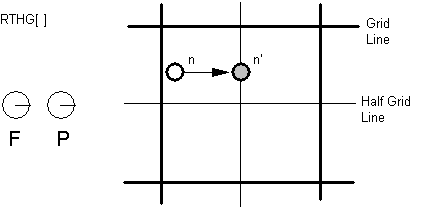
Sets the round_state variable to state 0 (hg). In this state, the coordinates of a point are rounded to the nearest half grid line.

Example:

Round To Grid
RTG[ ]

Code Range

0x18

Pops

Pushes

Sets

round_state

Affects

MDAP, MDRP, MIAP, MIRP, ROUND

Uses

freedom_vector, projection_vector


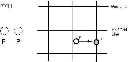
Sets the round_state variable to state 1 (g). In this state, distances are rounded to the closest grid line.

Example:

Round To Double Grid
RTDG[ ]

Code Range

0x3D

Pops

Pushes

Sets

round_state

Affects

MDAP, MDRP, MIAP, MIRP, ROUND

Uses

freedom_vector, projection_vector


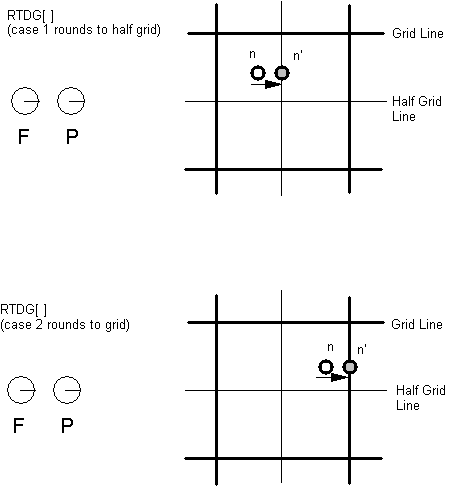
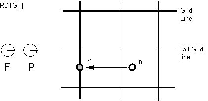
Sets the round_state variable to state 2 (dg). In this state, distances are rounded to the closest half or integer pixel.

Example:

Round Down To Grid
RDTG[ ]

Code Range

0x7D

Pops

Pushes

Sets

round_state

Affects

MDAP, MDRP, MIAP, MIRP, ROUND

Uses

freedom_vector, projection_vector


Sets the round_state variable to state 3 (dtg). In this state, distances are rounded down to the closest integer grid line.

Example:

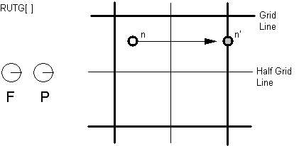
Round Up To Grid
RUTG[ ]

Code Range

0x7C

Pops

Pushes

Sets

round_state

Affects

MDAP, MDRP, MIAP, MIRP, ROUND

Uses

freedom_vector, projection_vector


Sets the round_state variable to state 4 (utg). In this state distances are rounded up to the closest integer pixel boundary.

Example:

Round OFF
ROFF[ ]

Code Range

0x7A

Pop

Pushes

Sets

round_state

Affects

MDAP, MDRP, MIAP, MIRP, ROUND

Uses

freedom_vector, projection_vector


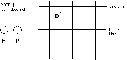
Sets the round_state variable to state 5 (off). In this state rounding is turned off.

Example:

Super ROUND
SROUND[ ]

Code Range

0x76

Pops

n: number decomposed to obtain period, phase, threshold

Pushes

Sets

round_state

Affects

MDAP, MDRP, MIAP, MIRP, ROUND


SROUND allows you fine control over the effects of the round_state variable by allowing you to set the values of three components of the round_state: period, phase, and threshold.

More formally, SROUND maps the domain of 26.6 fixed point numbers into a set of discrete values that are separated by equal distances. SROUND takes one argument from the stack, n, which is decomposed into a period, phase and threshold.

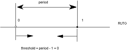
The period specifies the length of the separation or space between rounded values in terms of grid spacing.

The phase specifies the offset of the values from multiples of the period.

The threshold specifies the part of the domain that is mapped onto each value. More intuitively, the threshold tells a value when to "fall forward" to the next largest integer.

Only the lower 8 bits of the argument n are used. For SROUND gridPeriod is equal to 1.0 pixels. The byte is encoded as follows: bits 7 and 6 encode the period, bits 5 and 4 encode the phase and bits 3, 2, 1 and 0 encode the threshold as shown here.

period

0

period = gridPeriod/2

1

period = gridPeriod

2

period = gridPeriod*2

3

Reserved


phase

0

phase = 0

1

phase= period/4

2

phase = period/2

3

phase = gridPeriod*3/4


threshold

0

threshold = period -1

1

threshold = -3/8 * period

2

threshold = -2/8 * period

3

threshold = -1/8 * period


4

threshold = 0/8 * period

5

threshold = 1/8 * period

6

threshold = 2/8 * period

7

threshold =3/8 * period


8

threshold = 4/8 * period

9

threshold = 5/8 * period

10

threshold = 6/8 period

11

threshold = 7/8 * period


12

threshold = 8/8 * period

13

threshold = 9/8 * period

14

threshold = 10/8 * period

15

threshold = 11/8 * period


For example, SROUND(01:01:1000) maps numbers into the values 0.25, 1.25, 2.25, .... The numbers from -0.25 to 0.75 are mapped into 0.25. The range of numbers [0.75, 1.75) map into 1.25. Similarly, the numbers from [1.75, 2.75) map into the number 2.25 and so on.

Rounding occurs after compensation for engine characteristics, so the steps in the rounding of a number n are:

add engine compensation to n.

subtract the phase from n.

add the threshold to n.

truncate n to the next lowest periodic value (ignore the phase).

add the phase back to n.

if rounding caused a positive number to become negative, set n to the positive round value closest to 0.

if rounding caused a negative number of become positive, set n to the negative round value closest to 0.

the period parameters can have values of 1/2 pixel, 1 pixel, or 2 pixels.

the phase parameters can have values of 0 pixels, 1/4 pixel, 1/2 pixel, or 3/4 pixel.

the threshold parameters can have values of -3/8 period, -2/8 period,... 11/8 period. It can also have the special value largest-number-smaller-than-period which causes rounding equivalent to CEILING.

Super ROUND 45 degrees
S45ROUND[ ]

Code Range

0x77

Pops

n: ULONG decomposed to obtain period, phase, threshold (ULONG)

Pushes

Sets

round_state

Affects

MDAP, MDRP, MIAP, MIRP, ROUND


S45ROUND is analogous to SROUND. The gridPeriod is SQRT(2)/2 pixels rather than 1 pixel. It is useful for measuring at a 45 degree angle with the coordinate axes.

Set LOOP variable
SLOOP[ ]

Code Range

0x17

Pops

n: value for loop Graphics State variable (integer)

Pushes

Sets

loop

Affects

ALIGNRP, FLIPPT, IP, SHP, SHPIX


Pops a value, n, from the stack and sets the loop variable count to that value. The loop variable works with the SHP[a], SHPIX[a], IP[ ], FLIPPT[ ], and ALIGNRP[ ]. The value n indicates the number of times the instruction is to be repeated. After the instruction executes, the loop variable is reset to 1.

Set Minimum_ Distance
SMD[ ]

Code Range

0x1A

Pops

distance: value for minimum_distance (F26Dot6)

Pushes

Sets

minimum_distance


Pops a value from the stack and sets the minimum_distance variable to that value. The distance is assumed to be expressed in sixty-fourths of a pixel.

INSTruction Execution ConTRol
INSTCTRL[]

Code Range

0x8E

Pops

s: selector flag (int32)

value: USHORT (padded to 32 bits) used to set value of instruction_control.

Pushes

Sets

instruction_control


Sets the instruction control state variable making it possible to turn on or off the execution of instructions and to regulate use of parameters set in the CVT program. INSTCTRL[ ] can only be executed in the CVT program.

This instruction clears and sets various control flags in the rasterizer. The selector flag determines valid values for the value argument. The value determines the new setting of the raterizer control flag. In version 1.0 there are only two flags in use:

Selector flag 1 is used to inhibit grid-fitting. If s=1, valid values for the value argument are 0 (FALSE) and 1 (TRUE). If the value argument is set to TRUE (v=1), any instructions associated with glyphs will not be executed. For example, to inhibit grid-fitting when a glyph is being rotated or stretched, use the following sequence on the preprogram:

PUSHB[000] 6

/* ask GETINFO to check for stretching or rotation */

GETINFO[]

/* will push TRUE if glyph is stretched or rotated */

IF[]

/* tests value at top of stack */

PUSHB[000] 1

/* value for INSTCTRL */

PUSHB[000] 1

/* selector for INSTCTRL */

INSTRCTRL[]

/* based on selector and value will turn grid-fitting off */

EIF[]

Selector flag 2 is used to establish that any parameters set in the CVT program should be ignored when instructions associated with glyphs are executed. These include, for example, the values for scantype and the CVT cut-in. If s=1, valid values for the value argument are 0 (FALSE) and 2 (TRUE). If the value argument is set to TRUE (v=2), the default values of those parameters will be used regardless of any changes that may have been made in those values by the preprogram. If the value argument is set to FALSE (v=0), parameter values changed by the CVT program will be used in glyph instructions.


SCAN conversion ConTRoL
SCANCTRL[ ]

Code Range

0x85

Pops

n: flags indicating when to turn on dropout control mode (16 bit word padded to 32 bits)

Pushes

Sets

scan_control


SCANCTRL is used to set the value of the Graphics State variable scan_control which in turn determines whether the scan converter will activate dropout control for this glyph. Use of the dropout control mode is determined by three conditions:

Is the glyph rotated?

Is the glyph stretched?

Is the current setting for ppem less than a specified threshold?

The interpreter pops a word from the stack and looks at the lower 16 bits.

Bits 0-7 represent the threshold value for ppem. A value of FF in bits 0-7 means invoke dropout_control for all sizes. A value of 0 in bits 0-7 means never invoke dropout_control.

Bits 8-13 are used to turn on dropout_control in cases where the specified conditions are met. Bits 8, 9 and 10 are used to turn on the dropout_control mode (assuming other conditions do not block it). Bits 11, 12, and 13 are used to turn off the dropout mode unless other conditions force it. Bits 14 and 15 are reserved for future use.

Bit

Meaning if set

8

Set dropout_control to TRUE if other conditions do not block and ppem is less than or equal to the threshold value.

9

Set dropout_control to TRUE if other conditions do not block and the glyph is rotated.

10

Set dropout_control to TRUE if other conditions do not block and the glyph is stretched.

11

Set dropout_control to FALSE unless ppem is less than or equal to the threshold value.

12

Set dropout_control to FALSE unless the glyph is rotated.

13

Set dropout_control to FALSE unless the glyph is stretched.

14

Reserved for future use.

15

Reserved for future use.


For example

0x0000

No dropout control is invoked

0x01FF

Always do dropout control

0x0A10

Do dropout control if the glyph is rotated and has less than 16 pixels per-em


The scan converter can operate in either a "normal" mode or in a "fix dropout" mode depending on the value of a set of enabling and disabling flags.

SCANTYPE
SCANTYPE[ ]

Code Range

0x8D

Pops

n: 16 bit integer

Pushes

Sets

scan_control


Pops a 16-bit integer whose value is used to determine which rules the scan converter will use. If the value of the argument is 0, the fast scan converter will be used. If the value of the integer is 1 or 2, simple dropout control will be used. If the value of the integer is 4 or 5, smart dropout control will be used. More specifically,

if n=0 rules 1, 2, and 3 are invoked (simple dropout control scan conversion including stubs)

if n=1 rules 1, 2, and 4 are invoked (simple dropout control scan conversion excluding stubs)

if n=2 rules 1 and 2 only are invoked (fast scan conversion; dropout control turned off)

if n=3 same as n = 2

if n = 4 rules 1, 2, and 5 are invoked (smart dropout control scan conversion including stubs)

if n = 5 rules 1, 2, and 6 are invoked (smart dropout control scan conversion excluding stubs)

if n = 6 same as n = 2

if n = 7 same as n = 2

The scan conversion rules are shown here:

Rule 1

If a pixel's center falls within the glyph outline, that pixel is turned on.

Rule 2

If a contour falls exactly on a pixel's center, that pixel is turned on.

Rule 3

If a scan line between two adjacent pixel centers (either vertical or horizontal) is intersected by both an on-Transition contour and an off-Transition contour and neither of the pixels was already turned on by rules 1 and 2, turn on the left-most pixel (horizontal scan line) or the bottom-most pixel (vertical scan line). This is "Simple" dropout control.

Rule 4

Apply Rule 3 only if the two contours continue to intersect other scan lines in both directions. That is, do not turn on pixels for 'stubs.' The scanline segments that form a square with the intersected scan line segment are examined to verify that they are intersected by two contours. It is possible that these could be different contours than the ones intersecting the dropout scan line segment. This is very unlikely but may have to be controlled with grid-fitting in some exotic glyphs.

Rule 5

If a scan line between two adjacent pixel centers (either vertical or horizontal) is intersected by both an on-Transition contour and an off-Transition contour and neither of the pixels was already turned on by rules 1 and 2, turn on the pixel which is closer to the midpoint between the on-Transition contour and off-Transition contour. This is "Smart" dropout control.

Rule 6

Apply Rule 5 only if the two contours continue to intersect other scan lines in both directions. That is, do not turn on pixels for 'stubs.'


New fonts wishing to use the new modes of the ScanType instruction, but still wishing to work correctly on old rasterizers that don't recognize the new modes should:

First execute a ScanType instruction using an old mode which will give the best approximation to the desired new mode (e.g. Simple Stubs for Smart Stubs), and then

Immediately execute another ScanType instruction with the desired new mode.

Set Control Value Table Cut In
SCVTCI[ ]

Code Range

0x1D

Pops

n: value for cut_in (F26Dot6)

Pushes

Sets

control_value_cut_in

Affects

MIAP, MIRP


Sets the control_value_cut_in in the Graphics State. The value n is expressed in sixty-fourths of a pixel.

Increasing the value of the cut_in will increase the range of sizes for which CVT values will be used instead of the original outline value.

Set Single_Width_Cut_In
SSWCI[ ]

Code Range

0x1E

Pops

n: value for single_width_cut_in (F26dot6)

Pushes

Sets

single_width_cut_in

Affects

MIAP, MIRP


Sets the single_width_cut_in in the Graphics State. The value n is expressed in sixty-fourths of a pixel.

Set Single-width
SSW[ ]

Code Range

0x1F

Pops

n: value for single_width_value (FUnits)

Pushes

Sets

single_width_value


Sets the single_width_value in the Graphics State. The single_width_value is expressed in FUnits.

Set the auto_flip Boolean to ON
FLIPON[ ]

Code Range

0x4D

Pops

Pushes

Sets

auto_flip

Affects

MIRP


Sets the auto_flip Boolean in the Graphics State to TRUE causing the MIRP instructions to ignore the sign of Control Value Table entries. The default auto_flip Boolean value is TRUE.

Set the auto_flip Boolean to OFF
FLIPOFF[ ]

Code Range

0x4E

Pops

Pushes

Sets

auto_flip

Affects

MIRP


Set the auto_flip Boolean in the Graphics State to FALSE causing the MIRP instructions to use the sign of Control Value Table entries. The default auto_flip Boolean value is TRUE.

Set Angle _Weight
SANGW[ ]

Code Range

0x7E

Pops

weight: value for angle_weight

Pushes

Sets

angle_weight


SANGW is no longer needed because of dropped support to the AA (Adjust Angle) instruction. AA was the only instruction that used angle_weight in the global graphics state.

Pops a weight value from the stack and sets the value of the angle_weight state variable accordingly.

Set Delta_Base in the graphics state
SDB[ ]

Code Range

0x5E

Pops

n: value for the delta_base (ULONG)

Pushes

Sets

delta_base

Affects

DELTAP1, DELTAP2, DELTAP3, DELTAC1, DELTAC2, DELTAC3


Pops a number, n, and sets delta_base to the value n. The default for delta_base is 9.

Set Delta_Shift in the graphics state
SDS[ ]

Code Range

0x5F

Pops

n: value for the delta_shift (ULONG)

Pushes

Sets

delta_shift

Affects

DELTAP1, DELTAP2, DELTAP3, DELTAC1, DELTAC2, DELTAC3


Sets delta_shift to the value n. The default for delta_shift is 3.