| Field | Offset | Length | Value |
| Signature | 00h | 4 BYTES | $PnP (ASCII) |
| Version | 04h | BYTE | 10h |
| Length | 05h | BYTE | 21h |
| Control field | 06h | WORD | Varies |
| Checksum | 08h | BYTE | Varies |
| Event notification flag address | 09h | DWORD | Varies |
| Real Mode 16-bit offset to entry point | 0Dh | WORD | Varies |
| Real Mode 16-bit code segment address | 0Fh | WORD | Varies |
| 16-Bit Protected Mode offset to entry point | 11h | WORD | Varies |
| 16-Bit Protected Mode code segment base address | 13h | DWORD | Varies |
| OEM Device Identifier | 17h | DWORD | Varies |
| Real Mode 16-bit data segment address | 1Bh | WORD | Varies |
| 16-Bit Protected Mode data segment base address | 1Dh | DWORD | Varies |
| bits 15:2: Reserved (0) | ||
| bits 1:0: | Event notification mechanism | |
| 00=Event notification is not supported | ||
| 01=Event notification is handled through polling | ||
| 10=Event notification is asynchronous (at interrupt time) |
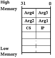 Figure 4.4.1 - 16-bit Stack Frame on 32-bit Stack
The Plug and Play system BIOS can determine whether the stack is a 32-bit stack or a 16-bit stack in 16-bit and 32-bit environments through the use of the LAR - Load Access Rights Byte Instruction. The LAR instruction will load the high order doubleword for the specified descriptor. By loading the access rights for the current stack segment selector, the system BIOS can check the B-bit (Big bit) of the stack segment descriptor which identifies the stack segment descriptor as either a 16-bit segment (B-bit clear) or a 32-bit segment (B-bit set).
In addition to executing the LAR command to get the entry point stack size, the BIOS code should avoid ADD BP,X type stack operands in runtime service code paths. These operands carry the risk of faulting if the 32-bit stack base happens to be close to the 64K boundary. For the 16-Bit Protected Mode interface, it is assumed that the segment limit fields will be set to 64K. The code segment must be readable. The current I/O permission bit map must allow accesses to the I/O ports that the system BIOS may need access to in order to perform the function. The current privilege level (CPL) must be less than or equal to I/O privilege level. This will allow the Plug and Play BIOS to use sensitive instructions such as CLI and STI.
The OEM Device Identifier field provides a means for specifying a device identifier for the system. The format of the OEM Device Identifier follows the format specified for EISA product identifiers. A system identifier is not required and if not specified, this field should be 0.
The entry point is assumed to have a function prototype of the form,
int FAR (*entryPoint)(int Function, ...);
and follow the standard 'C' calling conventions.
System software will interface with all of the functions described in this specification by making a far call to this entry point. As noted above, the caller will pass a function number and a set of arguments based on the function being called. Each function will also include an argument which specifies a data selector which will allow the Plug and Play BIOS to access and update variables within the system BIOS memory space. This data selector parameter is required for protected mode callers. The caller must create a data segment descriptor using the 16-bit Protected Mode data segment base address specified in the Plug and Play Installation Structure, a limit of 64KB, and the descriptor must be read/write capable. Real mode callers are required to set this parameter to the Real Mode 16-bit data segment address specified in the Plug and Play Installation Structure.
Any functions described by this specification which are not supported should return the FUNCTION_NOT_SUPPORTED return code. The function return codes are described in Appendix C of this specification.
4.4.1 System BIOS Plug and Play Compliance - "$PnP"
This section describes the support that is guaranteed by the "$PnP" string in the Plug and Play Installation Check structure and specifies the BIOS support required to be Plug and Play compliant for systems with different characteristics. A Plug and Play compliant system will guarantee:
Figure 4.4.1 - 16-bit Stack Frame on 32-bit Stack
The Plug and Play system BIOS can determine whether the stack is a 32-bit stack or a 16-bit stack in 16-bit and 32-bit environments through the use of the LAR - Load Access Rights Byte Instruction. The LAR instruction will load the high order doubleword for the specified descriptor. By loading the access rights for the current stack segment selector, the system BIOS can check the B-bit (Big bit) of the stack segment descriptor which identifies the stack segment descriptor as either a 16-bit segment (B-bit clear) or a 32-bit segment (B-bit set).
In addition to executing the LAR command to get the entry point stack size, the BIOS code should avoid ADD BP,X type stack operands in runtime service code paths. These operands carry the risk of faulting if the 32-bit stack base happens to be close to the 64K boundary. For the 16-Bit Protected Mode interface, it is assumed that the segment limit fields will be set to 64K. The code segment must be readable. The current I/O permission bit map must allow accesses to the I/O ports that the system BIOS may need access to in order to perform the function. The current privilege level (CPL) must be less than or equal to I/O privilege level. This will allow the Plug and Play BIOS to use sensitive instructions such as CLI and STI.
The OEM Device Identifier field provides a means for specifying a device identifier for the system. The format of the OEM Device Identifier follows the format specified for EISA product identifiers. A system identifier is not required and if not specified, this field should be 0.
The entry point is assumed to have a function prototype of the form,
int FAR (*entryPoint)(int Function, ...);
and follow the standard 'C' calling conventions.
System software will interface with all of the functions described in this specification by making a far call to this entry point. As noted above, the caller will pass a function number and a set of arguments based on the function being called. Each function will also include an argument which specifies a data selector which will allow the Plug and Play BIOS to access and update variables within the system BIOS memory space. This data selector parameter is required for protected mode callers. The caller must create a data segment descriptor using the 16-bit Protected Mode data segment base address specified in the Plug and Play Installation Structure, a limit of 64KB, and the descriptor must be read/write capable. Real mode callers are required to set this parameter to the Real Mode 16-bit data segment address specified in the Plug and Play Installation Structure.
Any functions described by this specification which are not supported should return the FUNCTION_NOT_SUPPORTED return code. The function return codes are described in Appendix C of this specification.
4.4.1 System BIOS Plug and Play Compliance - "$PnP"
This section describes the support that is guaranteed by the "$PnP" string in the Plug and Play Installation Check structure and specifies the BIOS support required to be Plug and Play compliant for systems with different characteristics. A Plug and Play compliant system will guarantee:
| System Characteristics | Required Functions | Optional Functions |
| Systems with embedded devices on the systemboard. | 00h, 01h, 02h | |
| Proprietary bus devices or local ISA devices on the systemboard. | ||
| Systems that support docking to expansion bases | 03h, 04h, 05h | |
| Reserved | 06h, 07h, 08h | |
| Systems with an ISA expansion bus | 40h | 09h, 0Ah |
| ESCD Interface Functions | 41h, 42h, 43h | |
| Systems supporting APM 1.1 (and greater) | 0Bh |
| Example Systems | Runtime Services | Event | ISA Allocated Resource Support | ISA PnP Isolation |
| Systems without an ISA bus; limited or a variety of boot devices; No Dynamic Events | Required | Not Required | Not Required | Not Required |
| Systems without an ISA bus; limited or a variety of boot devices; Dynamic Events supported | Required | Required | Not Required | Not Required |
| Systems with an ISA bus; No Dynamic Events | Required | Not Required | Not Required | Required |
| Systems with an ISA bus; Dynamic Events supported | Required | Required | Not Required | Required |