Herman Rodent
Microsoft Developer Network Technology Group
Created: February 1, 1994
Click to open or copy files in the ANIM32 sample application for this technical article.
This article follows some nine months after my original article "Animation in Windows," which described how to implement a sprite-based animation engine in Microsoft® Windows® version 3.1. Since that article was written, I have converted my development environment from Windows 3.1 and the C language to Windows NT™, Visual C++™, and the Microsoft Foundation classes (MFC). After the initial learning curve of C++ and MFC, I set out to prove that what you could do in C, you could do in C++, and what's more, do it so that the final executable could run unmodified on Windows NT, Windows 95 (the next version of the Windows operating system), and Windows 3.1 (under Win32s™). This article and the accompanying sample application, ANIM32, is the result of that work. The article discusses the following points:
Microsoft® Visual C++™ and the Microsoft Foundation Class Library (MFC) make creating applications with a document/view architecture very simple. MFC provides a comprehensive framework from which many different types of application can be constructed. After having learned the C++ language and the way of document/view architecture under MFC, I decided to see what the limits were. Were there any applications that couldn't be created with MFC? Did MFC prevent me from writing efficient code, or did it always provide a head start for whatever type of application I wanted to create?
I experimented with creating various applications that had no window borders, used funny pop-up menus, made messaging application programming interface (MAPI) calls to our electronic mail system, handled audio playback and recording, and a few other features as well. In each case, I found that with a little research—usually in the Development Library—I could do exactly what I wanted to do.
So much for restrictions. The next test was performance. Would MFC be able to do something that required very close control of the Microsoft Windows® application programming interfaces (APIs) being used? What better test than to try to create an animation engine? And so I decided to port my original Sprites sample to the world of MFC. And the result? No, MFC doesn't get in the way. In fact, MFC provided a convenient way to structure the data and functionality, delivering the promise of C++ without compromising the performance at all.
This article describes the road I followed to create the ANIM32 sample application. The trip is not in chronological order because the road I followed had many a twisting turn leading to a dead end. Instead, I have grouped together all the facts about a particular aspect of the development in one place.
You don’t need to read the previous article, "Animation in Windows," to understand this one. This article contains all you need to know to implement a basic sprite engine in Visual C++.
Initially, I simply wanted to port the Sprites sample application from C to C++ with the MFC framework. After a little consideration, I decided to improve the original architecture a little so that each sprite might one day have its own thread and behave truly independently. The ANIM32 sample doesn't go as far as implementing a multiple-thread version of the engine. That work should appear in a later article when I've finished studying Ruediger Asche's articles in the Microsoft Development Library on avoiding thread deadlocks—"Detecting Deadlocks in Multithreaded Win32 Applications," "The Implementation of DLDETECT.EXE," and "Putting DLDETECT to Work."
The goals for the sample application were as follows:
As things turned out, the executable file runs on Windows NT version 3.1, Windows 95, the beta version of Windows NT version 3.5, and Windows version 3.1 (under Win32s™). The sample was built and run on a MIPS machine running Windows NT. No attempt was made to build the application for Windows 3.1 directly, as I anticipated that any work being done by you as a result of reading this article would be done for the brave new 32-bit world.
Because this code was written to be 32-bit only, I have abandoned to a large degree the use of artificial types such as LONG, which are commonly used in programming for Windows to aid 16-to-32-bit portability. Instead, I have reverted to my Kernighan and Ritchie roots (The C Programming Language, 2nd edition, 1988) and used the trusty int wherever I felt the need. Along the same lines, I have used malloc rather than one of the many Windows memory allocation functions. If you want to know about the pros and cons of this approach, read the excellent articles in the Microsoft Development Library by Randy Kath concerning the memory architecture of Windows NT—"Managing Virtual Memory in Win32," "Managing Memory-Mapped Files in Win32," and "Managing Heap Memory in Win32."
You will find the use of WORD, LONG, and the like where the code is used to access files or existing Windows data structures. I have used them here to ensure complete compatibility with Windows.
In debugging my code, I initially used the TRACE macros supplied with MFC. As I wanted to use the sample as a demonstration application and didn't want to always run it under Visual C++, I ported my own dprintf macros from my earlier work. I have implemented my own debugging macro support, which prints messages in a separate pop-up window. The window has its own menu to control the debug level as the application runs. Level 0 prevents any debug messages from appearing. Level 1 shows only error conditions. Level 2 shows entry to major functions; level 3 shows more procedural detail; and level 4 shows data dumps and timing information for critical function calls.
Code fragments included here in the article generally have the debug code, comments, and error-handling code stripped from them so that you can see the maximum amount of code in the least number of screen lines. Please refer to the actual code for more detail, and use the actual code for reference if it is found to be different from the code fragments in the article, because bug fixes and minor modifications to the code may happen after the article is written.
In the "Animation in Windows" article, I made the assumption that the reader would already be familiar with sprite animation techniques, and consequently, it wasn't necessary for me to describe them. Since writing the article, I have presented the material to a variety of audiences who would like to use animation in their applications, but have no idea where to start in implementing an engine, so this section is by way of an introduction to what sprites and rendering are all about. I should point out that I am, in my own opinion, not at all an expert on animation. The description that follows relates only to how I implemented my own application. There are more ways to skin this particular cat, but they are not described here.
I consider a sprite to be a picture with an irregular shape, possibly with transparent holes in it, that can be moved left, right, up, and down on the screen, and that has depth, which is called z-order. So a sprite is a picture with x, y, and z coordinates. I use the client area of a window in its default mapping mode of MM_TEXT, so the point (0, 0) is the top-left corner of the window. The x values increase to the right, and y values increase toward the bottom. For the z-order, I chose to have low z values at the front and high values at the back.
One of the practical problems I faced was how to define what bits of the picture are transparent. I chose to do this by defining a single color, which is used only to paint the transparent areas of the image. Since a Windows device-independent bitmap (DIB) or device-dependent bitmap (DDB) has no way to store information about which color should be considered as transparent, I chose to always have the top-left pixel define the transparent color. This works well in practice because generally sprites are irregular shapes and the top-left corner is almost always required to be transparent anyway. If you want a rectangular sprite, the penalty you pay is having one transparent line at either the top or the left side of the image.
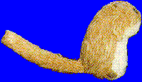
Figure 1 shows a picture of a famous rodent. The blue areas are to be the transparent ones (because the top-left pixel is blue). Note that this image is a 256-color DIB, so if you are viewing it on a 16-color VGA display, it isn't going to look quite as I intended—the graphics device interface (GDI) does try to map those colors for you, but the results are not worth writing home about.
Figure 1. An image of a famous rodent intended to be used as a sprite
Beware when creating 256-color images that the color you choose for transparency in any given image is an exact RGB value. If you have several blues in the image, for example, be sure you know which one is going to be used to define the transparent regions.
Creating an animation that doesn’t flicker as the sprites move requires the use of an off-screen buffer in which the image is composed before changes to the overall image are copied to the screen. The off-screen buffer image consists of a composition of the background image and the sprites that are (conceptually) in front of it. The image is built up by rendering the various component images in the correct order. Figure 2 shows a typical example of a background image and two sprites. The current state of the off-screen buffer and the screen image are shown.
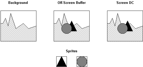
Figure 2. The initial state of the images, buffer, and screen
Figure 3 shows the current position of the sprites, the new position we would like to render them in, and the rectangular region of the screen affected by the change.
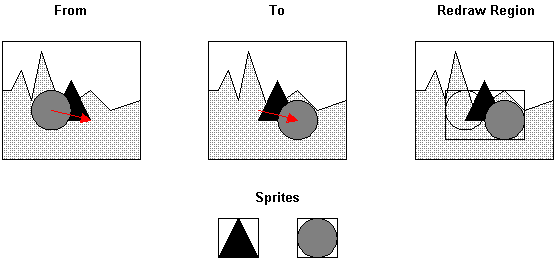
Figure 3. The task: moving the circle to the other side of the triangle sprite
Figure 4 shows the first step in constructing the new image, which is to copy a rectangle from the background image to the off-screen buffer to remove all sprites from the area that is changing. Note that the triangular sprite is not moving, so it doesn’t need to be totally erased. More about computing the dirty region later.
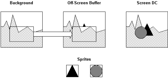
Figure 4. Step 1: Copy the background rectangle.
The next step is to render the sprites. This is done by starting with the sprite with the highest z-order and drawing it in place. Then the sprite in front of it is drawn and so on until all sprites have been rendered. Note that rendering the sprite means copying only the bits that are not transparent to the off-screen buffer. Figure 5 shows the backmost sprite being rendered.
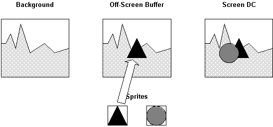
Figure 5. Step 2: Render the backmost sprite.
Figure 6 shows the frontmost sprite being rendered. In our case, there are only two sprites affected by the change.
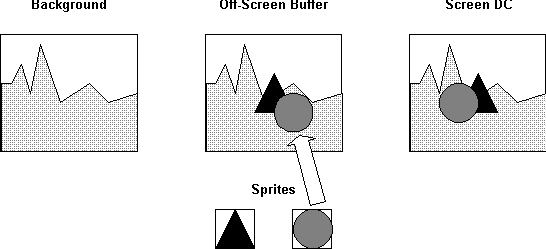
Figure 6. Step 3: Render the frontmost sprite.
Once all the sprites have been rendered in their new positions, the changed rectangle can be copied from the off-screen buffer to the screen, giving the effect of an instant update on the screen with no flicker. Figure 7 shows this step.
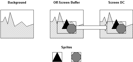
Figure 7. Step 4: Update the screen with the changes.
The final state is shown in Figure 8.
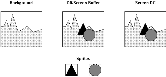
Figure 8. The final state
Remember, this isn’t the only way animation can be done; it’s just the way the ANIM32 sample does it.
Windows provides two kinds of image objects (other than cursors and icons, that is). The first of these is generally called a bitmap and is actually a device-dependent bitmap (DDB) created by the device driver. The second is the device independent bitmap (DIB), which can be created and manipulated directly by an application. Windows version 3.0 introduced the DIB to fix the problem of image portability with DDBs, which were simply an array of pixel values (1, 34, 228, and so on) with no color information. When they were selected into a device context (DC) and BitBlt was used to copy them to the screen, what essentially happened was that the bit values were copied from the bitmap to the screen memory. The problem was that on 256-color monitors, any given pixel value could map to any arbitrary RGB color value, and consequently, the image came out as garbage.
Windows 3.x bitmaps (DDBs and DIBs) have a color table that defines the color of each pixel value. (Actually this is not quite true for 16-, 24-, and 32-bits-per-pixel (bpp) bitmaps, but we’re primarily concerned with 8-bpp bitmaps here.)
To correctly show a bitmap’s colors, a palette can be created based on the bitmap’s color table. This palette is then selected and realized in the screen DC before the bitmap is drawn. In this way, the pixel values reference actual RGB values in the palette, and the image comes out correctly. DIBs fixed the problems of bitmap portability by defining a color table as part of the DIB header.
The advantage of using DIBs rather than DDBs in an application is that DIBs have a defined memory format and can be loaded into the application's memory space for direct pixel manipulation. This allows fancy wash effects and so on to be done with 24-bpp DIBs.
So far as this article is concerned, we will deal only with 8-bpp DIBs that have up to 256 colors. This matches nicely the most common display format, which is also 8-bpp and 256 colors.
The disadvantage of DIBs is that they cannot be used directly in most GDI calls. Instead, the application has to do a lot of the work and use GDI only for copying bits from the DIB to the screen. As it turns out, on a good display with a well-written display driver, an application that uses DIBs for animation can generally outperform one using DDBs.
In implementing ANIM32 on Windows NT 3.1, I encountered some performance problems (which are fixed in Windows NT 3.5) with using DIBs and decided to try using DDBs as an alternative. The results of this experiment are given later in the section about performance.
The ANIM32 sample application uses DIBs for all its image manipulation. Each sprite is based on a DIB. The background image is a DIB, and the off-screen buffer is a DIB, too. The images of the background and the sprites are rendered to the off-screen buffer by code in the application directly copying the required bits. No GDI calls are involved at all in creating the image in the off-screen buffer.
Screen updates are done by making a call to StretchDIBits, which copies bits directly from the off-screen DIB buffer to the screen video memory. StretchDIBits is implemented in the video device driver, so the call is typically very efficient. Figure 9 shows how the DIBs are used.
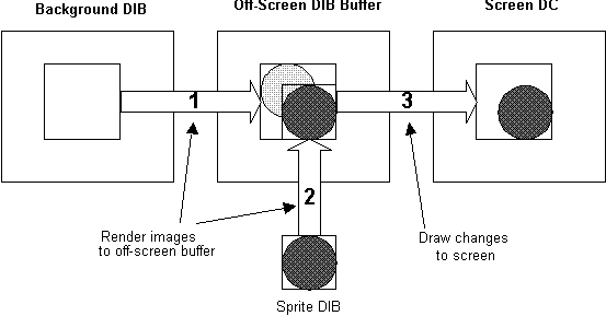
Figure 9. The rendering process with DIBs used as the images and as the off-screen buffer
ANIM32 implements its images and sprites as a set of C++ classes based on the base set provided by MFC. The application uses the document/view architecture provided by MFC. This might seem a bit strange for an animation, but I wanted to see if it were possible to simply add animation to the existing architecture, rather than having to start with something different. The end result is that the document/view architecture is fine as a base to start from. Figure 10 shows the set of classes used to create ANIM32 and the MFC classes they are derived from.
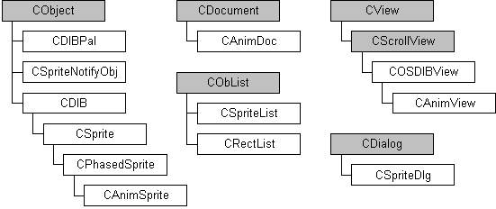
Figure 10. The set of classes used to create ANIM32
A document consists of a background image (from which a common palette is created) and a list of sprites. The sprite list also contains a function that is called by sprites as they move, in order to notify the list that a change of position has occurred. This is required so that the dirty region can be recorded for later painting. The callback object approach is only required if the sprites can move themselves, which was a goal for the application. At some point, each sprite will have its own thread. For now, there is only one thread in the application, and it is responsible for doing everything. It is perhaps more common to have one function update the positions of all the sprites and then go on to repaint the changed areas, which is how Sprites works and which is certainly simpler to implement if you don’t want your sprites to ever have lives of their own. Figure 11 shows how these objects are related.
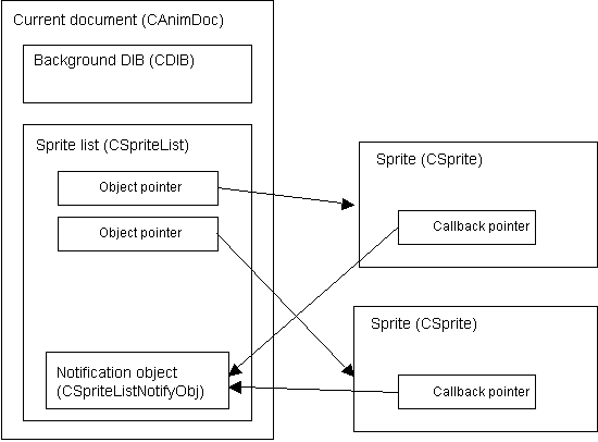
Figure 11. Object relationships in the document
The document has an associated view that is responsible for drawing to the screen via the off-screen buffer. In the typical case where a sprite moves, the dirty list is updated with the change information, and some time later the changes are rendered and the screen updated by the view. Figure 12 shows the order of events.
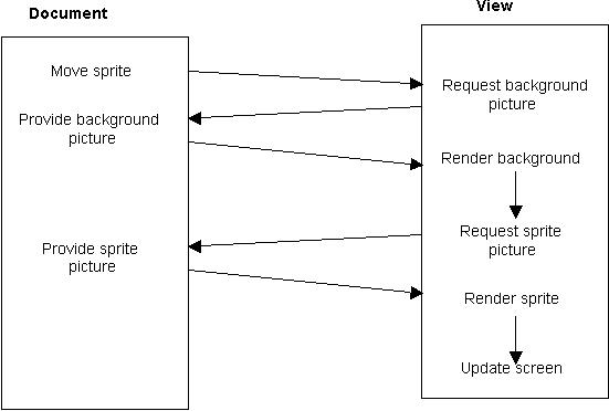
Figure 12. Event order for repainting the result of a sprite move
The view receives a call to its OnUpdate function, which begins the redrawing process. The view gets the background image from the document and renders it to the off-screen buffer. The view then gets each sprite in the correct z-order and renders them all to the off-screen buffer. Once the new image is complete in the off-screen buffer, the view calls its internal Draw function to copy the changed area to the screen.
Paint requests to the view are received through the view’s OnDraw function, which simply calls the view’s internal Draw function to copy the required rectangle from the off-screen buffer to the screen. In this way all OnDraw handling is done entirely by the COSDIBView object, and the application code is not required to do anything.
In order to make sprites appear to move on their own, the application must provide some mechanism to continuously change each sprite's position and request the view to render the changes to the screen. The final solution to this would be a separate thread for each sprite and a thread to handle the repaints. Because I wanted this sample to work on Windows 3.1 under Win32s, which doesn’t support threads, I had to find another way. I chose to use an idle loop in the same way that the Sprites application used it. MFC provides an OnIdle function in the CWinApp class for this purpose.
ANIM32 has a rather simplistic implementation of OnIdle that locates the current active CAnimDoc class document and calls its UpdateSpritePositions function. The document tells the sprite list object to update all sprite positions and then calls UpdateAllViews with a hint to say that only the current dirty list should be repainted.
How the sprites are actually moved is really very specific to the application. ANIM32 simply gives each one an x and y velocity and moves them accordingly. It’s not very exciting, but makes for a reasonable demo without the code getting all caught up in implementing paths for the sprites. It also freed me from having to include a method for defining the sprite paths. I included code to bring up a dialog box if a sprite is double-clicked. The dialog allows all the sprite parameters to be set.
In addition, ANIM32 has a feature that I call "phased sprites," which allows you to define a set of images for a sprite and combine them vertically into one DIB. You can then load the sprite image and tell the sprite how many phases to divide the image into. As the sprite moves, it changes the current phase of the image. In this way, you can implement rolling wheels or flying ducks. Figure 13 shows the image of a set of four phases for my own (not too well drawn) flying duck.
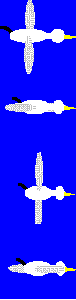
Figure 13. A DIB image of a four-phase sprite
Referring back to Figure 11, you can see that a list of the current sprite set is part of the document data. The order of the sprites in the list is not important, except when it comes to rendering. Each time we render a dirty rectangle to the off-screen buffer, we need to walk the sprite list in z-order, rendering any sprite that intersects the dirty rectangle we are working on.
Each sprite has its z-order value as a member variable. This is necessary so that multiple sprites may share a common value, which is convenient from an authoring point of view because a sprite may be assigned an arbitrary value that indicates it should be nearer the front (low value) or nearer the back (high value). If we relied on the list order to determine the z value, authoring would be much more painful.
When rendering the sprites, it is obviously very convenient to have them in the list in z-order. That way the rendering code can simply walk the list. ANIM32 is implemented so that adding a sprite to the list inserts it in front of the first member it finds from the top (low value) of the list that has the same or higher z value. In this way, if all sprites were given an arbitrary value of, say, 50 for z-order, the most recently added one will appear on top, which is what you would expect from a user's perspective.
Because of the requirement to keep the list ordered, changing the z-order of a sprite means moving its position in the list. I implemented this in a trivial way—remove the sprite from the list and reinsert it. The insertion code already handles the ordering. Figure 14 shows the ordering graphically.
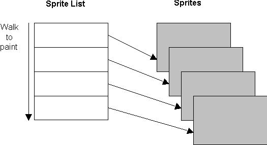
Figure 14. Sprite z-order management
The most expensive operation in moving a sprite is updating the screen, so whatever can be done to minimize the screen update calls will have a positive effect on performance. ANIM32 keeps a list of dirty rectangles that need to be repainted. In the older Sprites sample, when a repaint was about to happen, the dirty list was recursively walked, merging together any overlapping rectangles to avoid redundantly rendering the same region more than once. ANIM32 takes a slightly different, and much simpler, approach to this. When a dirty rectangle is added to the list, a test is made to see if it intersects the rectangle currently at the top of the list. If it does, the two rectangles are merged, leaving a rectangle that describes the combined region. No attempt is made to merge with the rectangle further down the list because it turns out that, in practice, there are not that many things going on in small animations. Figure 15 shows how rectangles are merged.
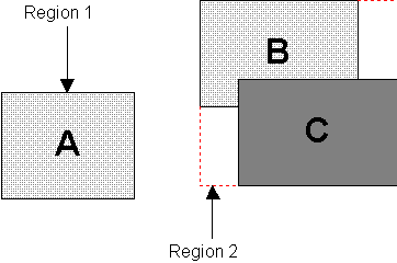
Figure 15. Overlapping dirty regions (B and C) combine to make one dirty region (Region 2)
If we care about performance, updating the screen from the off-screen buffer is the single most important aspect of the whole application.
The general order of events is:
We will discuss the wonders of palettes a little later. For now, take it that we have created a logical palette with all the colors we need for a given background and set of sprites, and that every DIB involved (background and sprites) has pixel values that index correctly into the logical palette.
Calling StretchDIBits with the DIB_PAL_COLORS option tells GDI that the pixel values in the DIB are indices into a table of palette indices and are not indices into the usual DIB color table. In this way, GDI won’t try to match color table colors in the DIB with the current palette. It will instead assume that you have done this already and simply work with the index values you supply. Tricky stuff, this, so let’s visualize it in Figure 16.
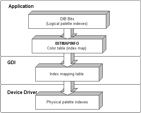
Figure 16. The flow of color index values
As you can see, a lot of tables are involved. Figure 16 is also somewhat simplified. To understand the process a little better, let’s look at how pixel values in the DIB end up on the screen. We need to understand this mechanism because, when it comes time to create the palette we are going to use, we need to be sure we get exactly what we want, or performance will suffer, as you will see. Figure 17 shows the same data flow as Figure 16, but with a little more detail.
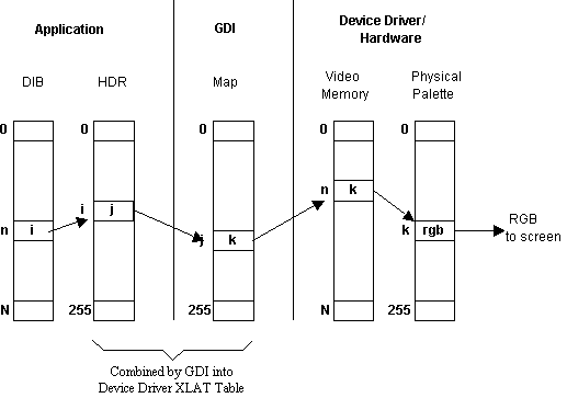
Figure 17. Pixel value to screen RGB value
The DIB contains a large number of pixels. Each pixel has a value in the range of 0 to 255, representing the index into the current logical palette. Referring to Figure 17, take pixel n in the DIB. It has a value of i. The pixel value represents an index into a 256-entry table in the DIB header, which contains yet another index value. So looking at the ith entry in the header table, we find it has a value of j. This value is mapped by GDI through the current mapping table for the application (more of this later). So the jth entry of the map has a value of k. This value (k) is stored in the video hardware memory at the correct pixel position. The display adapter hardware reads the memory and finds a value of k, which is used as an index into the hardware color palette. The kth entry in the color palette contains the actual RGB values that are sent to the digital-to-analog converters (DACs) that generate the analog signal sent to the monitor, which, you hope, shows a pixel of the color you set out to show.
It isn’t hard to see that an incorrect value in one of several places results in the wrong colors coming out at the end of the process. I have also omitted telling you how the colors of your logical palette end up in the physical hardware palette. That’s quite a subject in itself. We’ll look at some of what goes on a little later. For the full story, look at Ron Gery’s article in the Development Library on how the Windows Palette Manager works, "The Palette Manager: How and Why."
Now let’s look at how all this works for ANIM32. When ANIM32 calls StretchDIBits, the header that describes the DIB and contains the index mapping table marked HDR in Figure 17 actually contains a 1:1 table. So in index position 0, it has a value of 0, 1 in position 1, and so on. In other words, we construct a table that tells GDI to treat the value of each pixel in the DIB as a direct index into the logical palette. GDI builds a mapping table by combining the index map we provide in the DIB header with the current color index map. This pixel translation table is sent to the device driver to do the actual translation from our DIB pixel value to the hardware palette index value.
It doesn’t take a lot to figure out that if, by some freak chance, the physical palette happened to contain the exact same values as our logical palette, the translation table given to the device driver would be 1:1, and in effect, the pixel values in the DIB would be the actual values that should be written to the screen, and therefore, no translation of the pixel values would be required.
So if the device driver were smart enough to detect the 1:1 table, it could save itself a lot of time and effort and not translate the image bits at all. That’s what it takes to be a smart Windows device driver. You might also notice that GDI could have figured this out, too, and simply informed the driver that no translation was to take place, by passing a NULL pointer instead of a pointer to the required translation table. Windows 3.1 doesn’t specify its device driver interface this way, but Windows NT 3.1 does. “Good deal,” you say, "I no longer have to trust the guy who wrote the device driver to make the test. GDI will make the test and the device driver will do what it’s told." Unfortunately, even though the device driver specification says Windows NT 3.1 drivers have to work this way, someone forgot to tell GDI to do the test, and the result is that on Windows NT 3.1, every pixel of every DIB is always translated, resulting in an incredible loss of performance.
Both Windows NT 3.5 and Windows 95 will fix this to work correctly. If the translation table is an identity mapping, where every entry is the same as its index value, GDI will pass a null translation table pointer to the device driver, and no translation will take place. The result of all this is that applications will get much better performance on every Windows NT 3.5 and Windows 95 platform.
That isn’t quite the end of the tale, though; two things remain: First, we still haven’t seen how to get our logical palette into the system physical palette (which isn’t all that simple), and I forgot to mention that both Windows NT 3.5 and Windows 95 will have a new API called CreateDIBSection, which makes calling StretchDIBits unnecessary.
Let’s assume we know what we’re doing with palettes and have worked out the right way to get an identity translation table, and GDI and the device driver are both doing what they are supposed to do. Now we can compare what happens on Windows 3.1 and Windows NT when StretchDIBits is called with the DIB_PAL_COLORS option. Figure 18 shows the case for Windows 3.1.
Figure 18. StretchDIBits(DIB_PAL_COLORS) on Windows 3.1
Got the message here? The bits go straight from the DIB memory to the screen memory. It doesn’t get any better than that. Working like this, a Windows-based application can draw to the screen just as fast as an application for MS-DOS® using direct access to the video memory can, given that both use an off-screen buffer for rendering.
Now that we’ve got all happy about Windows 3.1, let’s look at the same operation in Windows NT 3.1 in Figure 19.
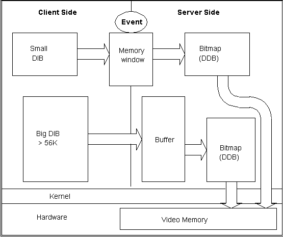
Figure 19. StretchDIBits(DIB_PAL_COLORS) in Windows NT
As you can see, this is just a bit more complicated than Windows 3.1 and, consequently, somewhat slower.
Memory for the DIB is allocated on the client side. To execute a call to StretchDIBits, GDI needs to create a DDB on the server side. Actually, DDBs are implemented as DIBs on the server side, but we still need to copy the bits because of process address space isolation. Right now, if a DIB is less than about 54K, it gets copied through the shared memory window. If it is larger than 54K, the Windows NT kernel is used to create a buffer on the server side and copy DIB bits to it. The server then creates a DDB from the buffer. Either way, the DIB is copied. To move the DDB to the screen, a blt function then gets called in the device driver, which copies the bits in the server-side buffer directly to the device's physical memory. The Windows NT kernel provides a way to map the physical memory of the display device into the process address space of the server. The video device driver runs in the server's process address space.
Just for comparison, if the application creates a DDB (bitmap), the memory for the DDB is allocated on the server side, and BitBlt can be used to transfer the bits directly to the video memory.
At this point, you would be forgiven for thinking that Windows NT isn’t the place to be using DIBs, and you'd be sort of right. Windows NT 3.5 and Windows 95 have a new API called CreateDIBSection, which eliminates all the nightmare problems of memory copying DIBs. Figure 20 shows what CreateDIBSection does.
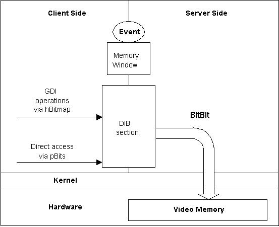
Figure 20. CreateDIBSection in Windows NT 3.5 and Windows 95
As you can see, things are much simpler. A common memory window is created to hold the DIB bits. The application on the client side can use the bitmap handle returned to select the bitmap into a DC and perform GDI operations on it, or it may use the pointer to the bits to access the DIB memory directly. Total control!
We can simply use BitBlt to transfer the DIB section bits to the display device memory, as is done with DDBs now. Note that using StretchDIBits won't work as well because there is no way to differentiate between one of these shared memory buffers and a chunk of memory allocated on the client side, so StretchDIBits will still have to copy the buffer to a separate buffer on the server side and call BitBlt from there, much as it does now.
Nobody likes dealing with palettes. Unlike WYSIWYG word processors, much of the time the result of using palettes in applications is WYSITB—What You See Is Totally Bizarre—as GDI happily provides an apparently random set of colors to your images.
We can do better than this, and indeed we must do better, because getting the 1:1 mapping table that is so important for the performance of StretchDIBits, and hence the application, depends on our understanding how palettes work. We’ll begin with an overview of how palettes work in Windows. For more detail, please refer to Ron Gery’s articles on palettes, "Using DIBs with Palettes" and "Palette Awareness," and on the Windows Palette Manager, "The Palette Manager: How and Why."
The physical palette is a part of the display adapter hardware and is managed by Windows via the display device driver. Windows manages the palette so that more than one application can attempt to use color at the same time. In dealing with animation, remember that the user is unlikely to be doing anything much else of importance while the animation runs (unless it’s really boring), so sharing the palette with other applications turns out to be of little interest to us.
Applications create and use logical palettes. The pixel values in your DIBs are index values into a logical palette. When you want to show a DIB, you give GDI the logical palette and the DIB bits. GDI maps your logical palette colors to the system (physical) palette and copies the DIB bits to the screen memory, thus displaying what you want. Or at least that’s what is supposed to happen.
In practice, the physical palette is shared among all applications and has some additional constraints applied by GDI that restrict what applications can do.
The currently active application gets first choice of the physical palette entries for its logical palette colors. So, if your animation is running, we can assume you are the active application, and you will get pretty much what you ask for. The main restriction is that the palette has 20 reserved system colors that you can’t (well, not easily, anyway) change. More on that later.
Let’s look at how your logical palette ends up in the physical palette, shown in Figure 21.
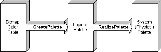
Figure 21. How colors get to the physical palette
The color information in the DIB color table is copied to a LOGPALETTE structure, and CreatePalette is called to create the logical palette. To use the palette, the application calls SelectPalette to select it into the DC and then RealizePalette to request GDI to map the entries of the logical palette currently selected into the DC to the physical palette.
The exact details of how this mapping is done are in Ron Gery’s articles, but here’s the gist of it for the foreground application: The first color in the logical palette is mapped first and so could be considered to be most important. GDI tries to find an existing entry in the physical palette with the correct RGB values. It starts at the zero index (BLACK) end of the palette and works up. If no match is found, GDI looks for an unused palette entry and sets the RGB values to those of your logical palette. If there are no free entries left, GDI maps the color to the nearest one it can find. So, at the end of the sequence, maybe some of your logical palette made it through!
In practice, if your application is the foreground application, all the system palette entries will be set to the unused condition, with the exception of the first ten and the last ten, which contain the reserved system colors. So if your logical palette has 236 colors or fewer, they should all end up in the physical palette.
Watch out for the case where your palette has two entries that are the same. This can happen. In this case, the second entry will get mapped to the first one because GDI always searches for a match before adding a new entry. You can stop this from happening by using the PC_NOCOLLAPSE flag, which tells GDI not to try to map the color to an existing one. Be careful here, though. If your logical palette already has the ten system colors at the bottom and ten at the top, you don’t want the PC_NOCOLLAPSE flag set for these entries, or it will create redundant entries for them in the system palette, which means you’ll run out of free slots if your logical palette is large.
Some time back I mentioned that StretchDIBits would go a lot faster if we had an identity mapping table, and that one of the problems was how to ensure that the physical palette entries exactly matched the logical palette entries. There are two approaches to this: The first is simple but can be destructive in some cases, and the second is rather more complex but results in a higher success rate.
In the simplest case, we can use the GetSystemPaletteEntries API to copy the first ten and the last ten system colors to our DIB color table so that they occupy the first and last ten positions of the DIB color table respectively. For all the other 236 entries, we set the PC_NOCOLLAPSE flag and create a palette from the table. When this palette is realized, what should happen is that the system color entries get mapped to their counterparts in the system palette, and the 236 middle entries get dropped into the system palette directly, starting at location 10.
This solution works very well, provided that the original DIB color table had similar colors to the system set in its first and last ten slots. If not, the DIB loses color information, and what is worse, the pixels of the DIB that referenced the first and last ten positions of the color table are now mapped to the ghastly dayglo system colors, resulting in a generally trashed image.
So if you are prepared to guarantee that your DIB color table is always authored to have system colors in the first and last ten positions, this is the way to go.
If you want to be able to import any DIB and still guarantee a 1:1 palette match, you will have to do a little more work. The problem here is that, in general, the first entry in the DIB color table is considered to be the most important color, and so on. This means that we can’t just blow these entries away—we have to find a way to get them into the physical palette.
The way to do this is to first create a logical palette for the entire DIB color table. Next, select the palette into the screen DC and realize it. GDI will take your set of colors and map them or insert them into the system palette as it sees fit. Now comes the clever bit.
Grab all 256 entries of the system palette, using GetSystemPaletteEntries, and put these values into your logical palette by calling SetPaletteEntries. Your logical palette now matches the system palette exactly. The only problem is that the DIB is all messed up because its pixel values no longer index the correct colors.
Next, take the 256 colors in the DIB color table, and for each one, use the GDI GetNearestPaletteColor function to find an entry in your new logical palette that matches (or is close). Use this information to create a translation table for the DIB pixel values and then walk through the DIB, and for every pixel, look up its new index value in the translation table and write it back to the DIB. The DIB pixels now map correctly to the logical palette, but some color information may have been lost if the original logical palette did not map well to the system palette (unlikely).
The final step is to reset the DIB color table to have the same RGB values as the new logical palette so that the DIB and its header are once more in sync. You only need worry about this if you'll want to use the RGB values later, which is not often the case for DIBs used for animation. Usually, we just want to get the right palette, and that’s it. The DIB is never saved, so we don’t care if it gets a bit mixed up along the way.
Being able to map a DIB to a given logical palette turns out to be a useful function to have because we can map all our sprites to one palette and thus ensure good performance and reasonable color accuracy. Obviously, we can’t have different palettes for the background and each of the sprites, so some form of color matching is essential. Of course, if all your images share a common color set to start with, you might think that you have no requirement to color match the sprites, but consider the case where we use the background DIB to create the palette and remap the DIB so it will come out right. Sprites created with the same original color table as the background image will no longer come out correctly because the colors got mixed up as a result of mapping to the system palette. So however you create your images, they will still need mapping at run time. This is still true if you use the simple mapping option and put the system colors in the DIB color tables to start with. The problem here is that different run-time systems have different RGB values for the same color (roll on, true color displays!), so a DIB authored with one set of system color RGB values won’t map exactly to a system with different RGB values.
The ANIM32 code includes wrappers around some of the major functions for rendering and screen updates, which measure the time taken to execute the function and show the result in the debug window. You need to be running at debug level 4 to see this, and you’ll get a lot of other information, too. I have also included some menu test options to allow you to try sprite rendering and blts with the same application running on different platforms.
Time has not allowed me to finish the performance optimization for this article, so I will present that in a follow-up article as soon as possible.
Once again I am indebted to Todd Laney for his willingness to come and draw on my whiteboard many of the diagrams that are so necessary to understanding this material. Many thanks, too, to Ron Gery for advice about palettes; to Michael Abrash, Patrick Haluptzok, and Eric Kutter of the Windows NT GDI team for information about how Windows NT does things; and to Scott Randell and Dean McCrory of the AFX group for answering many, many MFC questions. My wife, Tammy, deserves a special mention, too, for having put up with me working at home many nights to get the article and code done in time for the next edition of the Development Library.