Every graphical operation described in this chapter (including resizing, moving, and drawing) uses the coordinate system of the drawing area or container. Although you can use the coordinate system to achieve graphical effects, it is also important to know how to use the coordinate system to define the location of forms and controls in your application.
The coordinate system is a two-dimensional grid that defines locations on the screen, in a form, or other container (such as a picture box or Printer object). You define locations on this grid using coordinates in the form:
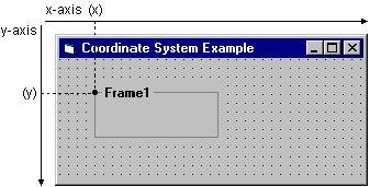
(x, y)
The value of x is the location of the point along the x-axis, with the default location of 0 at the extreme left. The value of y is the location of the point along the y-axis, with the default location of 0 at the extreme top. This coordinate system is illustrated in Figure 12.3.
Figure 12.3 The coordinate system of a form
The following rules apply to the Visual Basic coordinate system:
When you create code to resize or move a form, you should first check the Height and Width properties of the Screen object to make sure the form will fit on the screen.
The units of measure used to define locations along these axes are collectively called the scale. In Visual Basic, each axis in the coordinate system can have its own scale.
You can change the direction of the axis, the starting point, and the scale of the coordinate system, but use the default system for now. "Changing an Object’s Coordinate System" later in this chapter discusses how to make these changes.
By default, all Visual Basic movement, sizing, and graphical-drawing statements use a unit of one twip. A twip is 1/20 of a printer’s point (1,440 twips equal one inch, and 567 twips equal one centimeter). These measurements designate the size an object will be when printed. Actual physical distances on the screen vary according to the monitor size. "Changing an Object’s Coordinate System" describes how to select units other than twips.