Modeling a Bishop

Modeling a Chess Set

Modeling an Apple

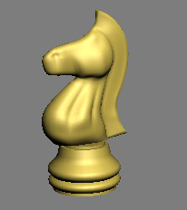
Modeling a Knight
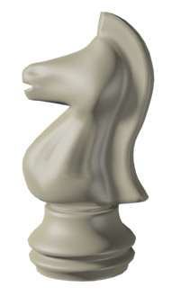
In this lesson, you will create a knight for
a chess set using custom splines and the Surface modifier. The Surface
modifier makes a 3D surface from an arrangement of intersecting
splines.
Modeling a knight presents a special set of
challenges: its unique contours demand that it be sculpted carefully.
The Surface modifier is ideal for this type of modeling.
Features and techniques covered in this lesson:
- Building
a spline cage.
- Refining
and Connecting spline vertices with new segments.
- Applying
and adjusting the Surface modifier.
- Using
the Symmetry modifier.
- Extruding
patches using the Edit Patch modifier.
Skill Level: Intermediate
Time to complete: 1 hour
Set
up the lesson:
- Load
the file knight_start.max from
the \intro_to_modeling folder.
The scene is empty except for a background picture
that you will use as reference as you model the knight. If you cannot
see the reference picture, follow these steps.
- Make
sure the Front viewport is selected and then press Alt+B.
- On
the dialog that appears, click the Files button.
- Locate
the ref-chess.jpg image
in the \intro_to_modeling folder and
double-click it.
Draw
the knight outline:
- Maximize
the Front view by pressing Alt+W.
-

 On the
Create panel, click Shapes, and then click Line.
On the
Create panel, click Shapes, and then click Line. - On
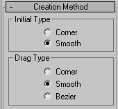
the Creation panel > Creation Method rollout, set both Initial
Type and Drag Type to Smooth. This will help set the base profile, given
the curved nature of the chess piece.
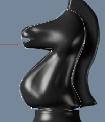
- Click
to create a contour for the knight. Do not take into account the
horse’s mane or the base for now. Keep in mind that this kind of
modeling does not require a lot of detail, so try to keep the number
of vertices to a minimum. You will adjust them later.
- Make
sure you close the spline by clicking the starting point.
-
 Go to
the Modify panel. On the Selection rollout, click Vertex.
Go to
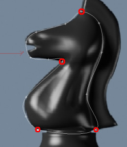
the Modify panel. On the Selection rollout, click Vertex. - Adjust
the positions of the vertices around the shape of the knight. Select
the following vertices.
- Right-click
and choose Bezier Corner from the quad menu.
- Use
the Select And Move tool to adjust the vertex handles so that the
profile fits the reference image better.
Create
the inner spline cage:
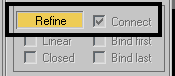
- You
will start adding detail where the head intersects the neck. On
the Modify panel > Geometry rollout, turn on Connect and then
click Refine.
NoteRefine
adds vertices to a spline. If the Connect option is on, all inserted
vertices will be connected by segments in the order they were created.
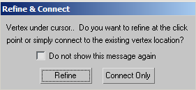
- Click
the Bezier Corner vertex at the intersection of the head and the
front of the neck.
A dialog opens:
This dialog points out that there is already
a vertex where you clicked. You still have the option to refine
the spline, adding yet another vertex very close to the existing
one, or you can simply use the existing vertex and connect it to
others you will be inserting. Typically, use the Connect Only method
when this warning appears.
- Turn
on the “Do not show this message again option” and click Connect
Only.
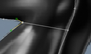
- Click
a point to the right at the back of the neck.
- Right-click
to finish the command. You now have an additional segment going
from the front to the back of the neck.
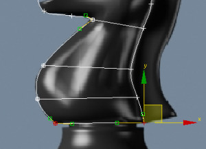
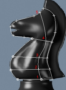
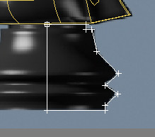
- Add
two more “levels” to the neck as shown in the illustration below.
- Use
Refine/Connect to add a vertical line of detail going from the neck
to the head.
- Continue
adding detail until the spline cage looks similar to the following
illustration.
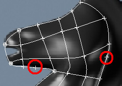
Delete
unwanted vertices:
The next step is to ensure that there are no
loose vertices on the spline cage. In this method of modeling, it
is essential that the spline cage is made of three- or four-sided
areas only.
- Make
sure the spline is still selected and that you are still at the Vertex
sub-object level.
- Look
for any loose vertices and select them.
- Press Delete to remove the unwanted vertices.
Make sure that a quad area has no more than four vertices, where segments
intersect.
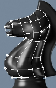
Fine-tune
the spline cage:
The next step is to adjust the spline cage to
get a nice flow of segments. When you refined the spline cage, you
introduced a number of intersecting segments and subsequently a
number of intersecting vertices. It is very important that these
vertices which share the same position in space be moved together.
- Make
sure the spline is still selected and that you are still at the Vertex
sub-object level.
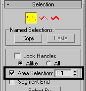
- In
the Selection rollout, turn on Area Selection and leave the value
at 0.1. This ensures that when you select a vertex by clicking it,
all vertices that are within the distance specified in the threshold
value get selected as well.
- Use
the Select And Move tool to relocate vertices to get a nice flow
of segments in the spline cage.
Give
the spline cage volume:
So far, you've built everything in the Front
viewport. The collection of segments lies therefore in the same
plane. In this step, you will adjust the spline cage so that it
starts shaping into a 3D volume.
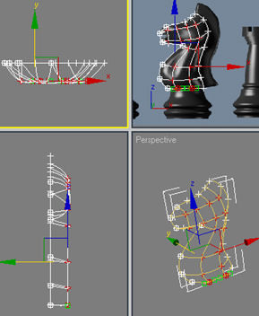
- If
the Front viewport is still maximized, press Alt+W to return to the four-way
viewport layout.
-
 Click
Zoom Extents All to see the spline cage in all four viewports.
Click
Zoom Extents All to see the spline cage in all four viewports. - Using
the Select tool and the Ctrl key,
select all the internal vertices plus the two center ones on the
bottom segment.
- In
the Top viewport, move the selected vertices down on the Y axis
(green axis).
- Keep
adjusting the position of these inner vertices to give the volume
a more interesting shape (narrower snout, thicker bottom neck, and
so on). Feel free to experiment but do not move the other vertices around
the perimeter; you'll need them to mirror the object later.
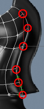
Adjust
the tangents on the perimeter:
- Select
all the vertices that run along the back of the neck, except for
the top one.
- Right-click
in the viewport and convert the selected vertices to Bezier Corner.
- Move
the angled tangents so they are in a more vertical position. This
will give the segments a stronger angle of attack as they meet the
mirror line.
TipIf
you try to move the tangents and find the direction locked in one
axis or another, press F8 to
constrain motion to the XY plane.
- Repeat
this procedure on the two vertices near the mouth, and those running
up the front of the neck.
- Repeat
the procedure on the vertices running along the top of the head,
but then use the Front viewport to make the tangents horizontal.
Test
the Surface Modifier
You will eventually mirror this spline arrangement
to make the other side of the knight, but before doing so, you need
to check the current setup to see if the Surface modifier works
on it.
The Surface modifier places a 3D surface over
each set of three- and four-sided polygons formed by the splines.
The polygons must be completely closed in order
for the Surface modifier to make the 3D surface. By trying out the
Surface modifier now, you can correct any “holes” in the surface
before you mirror the splines.
- With Line01 selected,
exit the Vertex sub-object level.
- From
the Modifier List, choose Surface from the Object-Space Modifiers
section. Depending on how you built your spline cage, the appearance
of the knight in the Perspective viewport might look solid or hollow.
- In
the Parameters rollout, try turning the Flip Normals option on or
off until the knight appears as shown on the right side of the illustration
above.
- Expand
the Line entry in the modifier stack and then click Vertex. Turn
on Show End Result so you can work on the spline cage and see the
effect of the Surface modifier simultaneously.
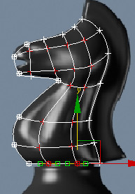
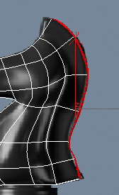
- In
the Front viewport, select the vertex on the neck where you see
a dip in the muscle tones. Right-click and convert that vertex to
Bezier Corner.
- In
the Top viewport, adjust the handles into a sharp inverted V. This
will help simulate the muscle tones on the neck. Keep an eye on
the Perspective viewport for reference.
- Experiment
with this vertex and others to mold a better-looking neck. You can
use this technique on other parts like the snout or the head as
well.
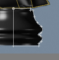
Refine
the mane line:
- Adjust
the Perspective viewport so that you are looking at the back of
the neck.
- Using
Connect/Refine, start from the vertex at the very top of the head
and work your way down to refine a mane line as shown in the following
illustration.
As you refine the segments, surface patches
temporarily disappear from view but reappear once you finish the
command. This is because you are introducing additional vertices
and this creates patch areas that have more than four vertices.
Once you are done refining the spline cage, however, the end result
is made up of quads again and therefore displays correctly.
- Exit
the Vertex sub-object level and then click the Surface modifier
to go to the top of the stack.
Mirror
the spline arrangement:
- If
you haven’t done so already, highlight the Surface modifier on the
modifier stack.
- From
the Modifier list choose Symmetry.
- On
the Parameters rollout, set Mirror Axis to Z.
- Orbit
around the object in the Perspective viewport to see the full 3D
object.
Extrude
and adjust the mane:
- Highlight
the Surface modifier on the modifier stack. From the Modifier list,
choose Edit Patch. This inserts an Edit Patch Modifier above the
Surface modifier and below the Symmetry Modifier.
-
 If necessary,
turn off Show End Result.
If necessary,
turn off Show End Result. You should be able to see only one half of the
knight in all viewports.
-
 On the
Selection rollout of the Patch modifier, choose the Patch button.
On the
Selection rollout of the Patch modifier, choose the Patch button. - In
the Perspective viewport, select the patches that make up the horse’s
mane.
- In
the Geometry rollout > Extrude & Bevel group, click the Extrude
button.
- Bring
the cursor close to the selected patches in the perspective view
and then click and drag to extrude the patches. Keep an eye on the Front
viewport for reference.
-
 On the
Selection rollout, switch from Patch to Vertex and turn on Show
End Results.
On the
Selection rollout, switch from Patch to Vertex and turn on Show
End Results. Because of the direction of the extrusion, you
need to adjust the vertex position to give the Symmetry modifier
a little help.
- In
the Front viewport, use region selection to select all vertices on
the outer edge of the mane. Use the Ctrl key if
necessary.
- In
the Top viewport, move the selected vertices up until they intersect
along the mirror line. Keep an eye on the other viewport to see if
the Symmetry modifier worked nicely to weld the seams.
NoteThis
was a rather simplistic way of adjusting the mirror line. Ideally,
you want to move the vertices individually or in groups, while at
the same time adjusting tangents for better effects.
- Adjust
the positions of the vertices and tangents in the Front viewport
to follow the reference image and create a nicely flowing mane.
Create
the base:
Even though you could have created the base
as part of the same spline cage, it is easier to build it as a separate
object and then attach the two objects together as a single mesh.
The base is a simple lathed object, much like the ones you created
in the previous lessons.
- From
the Create menu, choose Shapes > Line.
- On
the Creation Method rollout, set both the Initial Type and Drag
Type to Corner.
- In
the Front viewport, click a point in the top center of the base, just
below the knight.
- Hold
down the Shift key to
constrain the line to the vertical direction, and then click a point
at the bottom center of the base.
- Move
to the right and click a point at the bottom-right corner of the
base.
- Release
the Shift key and
go up the right side to create a rough profile of the base. Make
sure you close the spline when you are done.
- Go
to the Modify panel. On the Selection rollout, choose Vertex.
- On
the Geometry rollout, choose Fillet.
- Use
the Fillet tool to round off the vertices that need it.
- Exit
the Vertex sub-object level.
- From
the Modifier list, choose Lathe.
- Set
the Segments to 32 and turn Weld Core. In the
Align group, click Min.
NoteIf
you need further detail on how to create a lathed object, refer
to the first lesson in this tutorial: Modeling a Pawn.
Turn
the two objects into a single mesh:
- Make
sure the base is still selected. Right-click it and from the quad
menu, choose Convert to > Convert to Editable Mesh.
- On
the Edit Geometry rollout, click Attach and then click on the knight
in any viewport.
- Change
the object’s name to Knight.
The knight is now complete, unless you want
to add a mouth, which you can do by using Refine to add vertices,
and then moving the vertices.
Summary
In these lessons, you created four chess pieces,
learning different tools and methods in each case. Creating a pawn
taught you about working with splines and the lathe modifier. Creating
a bishop and a rook taught you about editing geometry and using
Boolean compound objects to add or subtract components. Finally,
you learned to model using a spline cage approach using the Surface
modifier with spline objects.