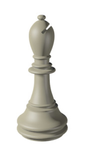
In this lesson you will model a bishop for the chess set. For the most part, the bishop is modeled the same way as the pawn, based on a profile shape and a lathe modifier. The difference is the gap that shows on the bishop’s head. You will use a Boolean object to achieve that result.
Features and techniques covered in this lesson:
Skill Level: Beginner
Time to complete: 15 minutes
Set up the lesson:
This file contains the profile of the bishop and a reference background image. If you cannot see the reference image, do the following steps.
Lathing the Bishop
 On the
main toolbar, click the Select tool. Select the spline representing
the bishop’s profile in any viewport.
On the
main toolbar, click the Select tool. Select the spline representing
the bishop’s profile in any viewport. With
the Spline selected, go to the Modify panel. From the Modifier list,
choose Lathe.
With
the Spline selected, go to the Modify panel. From the Modifier list,
choose Lathe.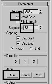
Create and position the box:
To create the gap in the bishop's head, you'll create a simple box and then subtract from the bishop model.
 Go to
the Modify panel and set the dimensions of the box as follows:
Go to
the Modify panel and set the dimensions of the box as follows:
 On the
main toolbar, click the Select And Rotate button. Rotate the box
in the Front viewport so that it is aligned with the gap on the
bishop’s head (in the reference image).
On the
main toolbar, click the Select And Rotate button. Rotate the box
in the Front viewport so that it is aligned with the gap on the
bishop’s head (in the reference image). Use
Select And Move to position the box on top of the gap.
Use
Select And Move to position the box on top of the gap.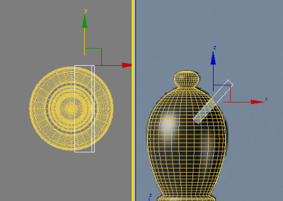
Create the slice with a Boolean operation:
When you perform a Boolean operation, the first object selected (in this case the bishop) is recognized as Operand A and the second object selected (in this case the box) as Operand B. You can then choose the type of operation to perform, whether it’s union, intersection, or subtraction, and, in the latter case, which operand to subtract from which.

In this lesson, you learned to remove geometry by cutting a hole in an object using Boolean operations.


