


Eliminating Errant Objects
With several different layout tab and paper space options available, objects in AutoCAD drawings can be widely separated throughout model space. As a result, objects that are located far from objects you want to import may be imported as well, greatly increasing the extents of the 3ds Max scene.
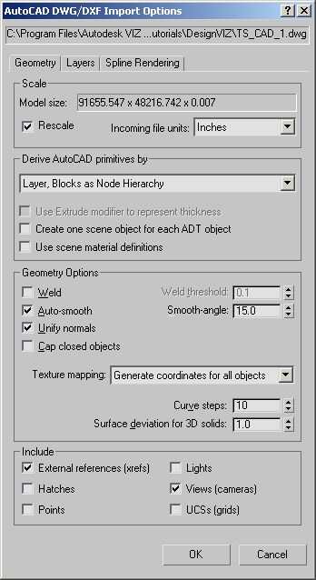
Set up the scene:
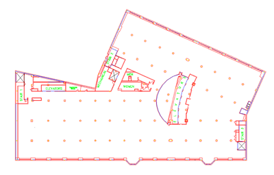
You're presented with a 2D drawing of an office building. Views have been set up to show plan and perspective views.
Delete errant objects:
When importing drawings into 3ds Max, it's important to manage layers effectively. If two objects on the same layer are separated by a great distance, you can start running into problems when the model is imported into 3ds Max.
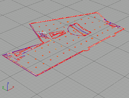
After the drawing is imported into 3ds Max, you'll notice that the viewport does not seem to have automatically zoomed to the extents of the imported drawing, thus causing the building to appear very small. This is a clear indication that an errant object is located a great distance from the scene. In the AutoCAD file, this object is located on the same layer as several other objects. When it is imported into 3ds Max, the objects sharing a layer are consolidated into a single entity. This wayward object cannot be deleted without also deleting the other objects that were imported with it.
The model space window is increased to show the entire drawing and since the main part of the drawing is condensed toward the lower left corner, it means the errant objects are somewhere in the upper right part of the viewport.
This time the file imports and displays correctly.
Be sure to close polylines:
Most designers who work primarily with AutoCAD create drawings with lines, arcs and circles. However, using polylines to create perimeter objects offers the quickest means of converting a 2D drawing into a 3D model. If drawn correctly, a polyline can be quickly extruded into a large solid surface like a poured concrete floor or a set of walls when the drawing is imported into 3ds Max.
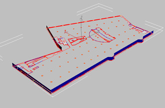
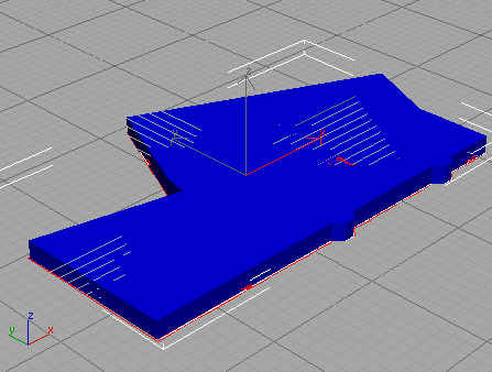
Notice that the spline that follows the perimeter of the building is extruded, but the top is not capped. This is an indication that the polyline was not closed in the AutoCAD drawing.
You have closed the gap in the polyline with an additional segment.
Only the objects on the LEASELN2 layer are imported.
This time the spline is capped.
Use File Link instead of Import:
The section you just completed made exclusive use of the import functionality of 3ds Max, but what would have been different if you had used the File Link Manager?
Doing this preserves the original drawing so the tutorial can be easily repeated.
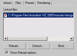
There is now an active link between the drawing in AutoCAD and 3ds Max.
Just as in the last section, the object is not capped due to the open polyline. Here's where the workflow process differs.
Fix the drawing and reload the link:
The red flag means the drawing has been updated.
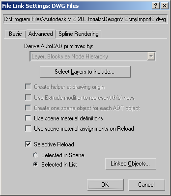
Since the Layer:LEASELN2 object was left selected after applying the extrude modifier only that object is reloaded from the drawing file. You could have also chosen from the list of linked objects by choosing the Layer:LEASELN2 object and clicking the Invert button.