Eliminating Errant Objects

Fixing Problems in CAD Models

Publishing to DWF

Resolving Other Common CAD Problems
Many companies
that use AutoCAD have vast archives of drawings that were originally
created many years ago. If you need to work with any of these drawings or
models, you can encounter problems in 3ds Max because of the
way older AutoCAD settings and objects are now interpreted. Such
common problems involve the following:
- Great
distances between objects in the CAD drawing and the drawing origin.
- The
use of the Thickness setting to display objects that projected into
the Z-axis, like extrusions.
- Imported
objects are not as smooth as you would like them.
- Unit
settings saved with the CAD model need rescaling.
- Texture
maps applied to a CAD model, are not found when the model is opened
in 3ds Max.
Drawing
origin placement:
Large scale drawings can pose problems due to
objects being placed at vast distances from the drawing origin.
- In
AutoCAD, open ts_cad_2.dwg or ts_cad_2_r14.dwg, depending on
the version of AutoCAD you're running.
- Choose
File menu > Save As and save the file as myImport3.dwg.
Once again, you're doing this to preserve the
original drawing so the tutorial can be easily repeated.
- Minimize
AutoCAD.
- Open 3ds Max or
choose File menu > Reset to reset the scene.
- Choose
File menu > Import and open myImport3.dwg.
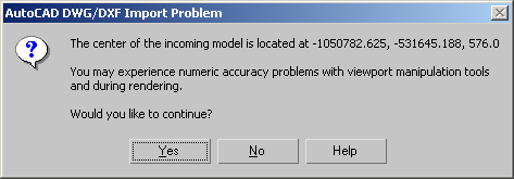
- On
the AutoCAD DWG/DXF Import Options dialog, turn on Rescale in the
Scale group and set the Incoming File Units to Feet.
- After
you click OK in the AutoCAD DWG/DXF Import Options dialog, a warning
indicates a potential problem with the file. Click Yes to proceed.
You’ll deal with this in a later step.
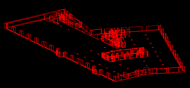
- In
the Perspective viewport,
zoom in to get a better view of the scene. You'll see several objects,
but not all of them on the ARWALL layer. These objects have vertical
faces with normals pointing in a number of directions.
- Reset
and minimize 3ds Max.
- Restore
AutoCAD and initiate the Move command.
- Select
the entire drawing and when asked to specify a base point, pick
a point near the center of the drawing.
- When
asked to specify a second point of displacement, enter the coordinates 0,0,0 and
press Enter.
This moves all the objects to the origin and
allows 3ds Max to more accurately determine location data.
- Perform
a Zoom Extents and then save the drawing.
- Restore 3ds Max and
choose File menu > Import.
- Open myImport3.dwg and
make sure to turn on Rescale.
- Set
the Incoming File Units to Feet and click the OK button.
You have now eliminated the warning message
that displays while importing the drawing.
For more information about the importance of
keeping the model close to the scene origin, refer to the System Unit Setup Dialog
topic.
Remove
line thickness:
While a drawing that contains lines with thickness
may give the appearance of a 3D model in AutoCAD, the lines only
display a framework. These can sometimes pose problems when imported
to 3ds Max so this section demonstrates how to quickly rest them.
- Continue
from the previous section and minimize 3ds Max.
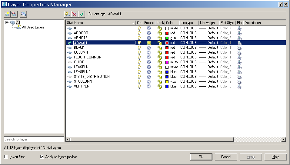
- Restore
AutoCAD and open the Layer Properties Manager and then make ARWALL
the current layer while freezing all the others.
- From
the menu, choose View > Named Views. In the View dialog, select
West, then click Set Current. Click OK.
The view adjusts to a perspective orientation.
Only lines have a Thickness value; therefore only they should be
selected so the values can be adjusted at the same time.
- Use
Zoom Extents to see the entire drawing.
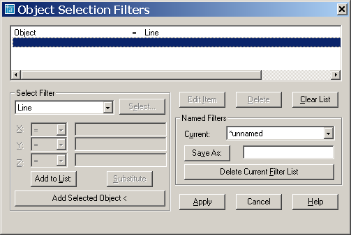
- At
the AutoCAD command line, type Change, press Enter, then type 'filter to
begin the command and open the Object Selection Filters dialog.
- From
the Select Filter drop-down list, choose Line, then click
Add To List, then Apply.
- Using
a selection window, select all the objects in the scene, then press Enter twice to return to the Change command.
Only the Line objects, as defined by the Filter
command, are selected.
- Type P (for
Properties) then T (for Thickness) and then enter 0 when
prompted to specify a new thickness. Press Enter twice.
The lines on ARWALL layer are now uniformly
at zero thickness.
- Save
the drawing, then import the file into 3ds Max again.
Adjust
smoothness:
There are two ways to deal with smoothness when
you import or file link a 3D object to 3ds Max. You can make
adjustments to smoothing groups that will give the illusion of smoothness
when a model is rendered or you can increase the number of faces
and surfaces of an object to get smooth results. This section addresses
the two methods of handling smoothness.
- Reset 3ds Max and
choose File menu > Import.
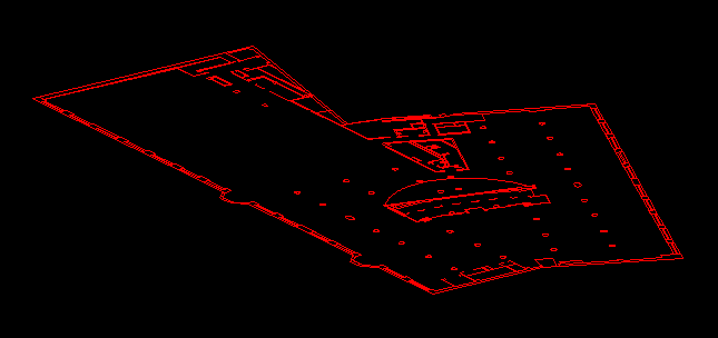
- Open canopy.dwg from the \tutorials\designviz folder,
stopping when the AutoCAD DWG/DXF Import Options dialog opens.
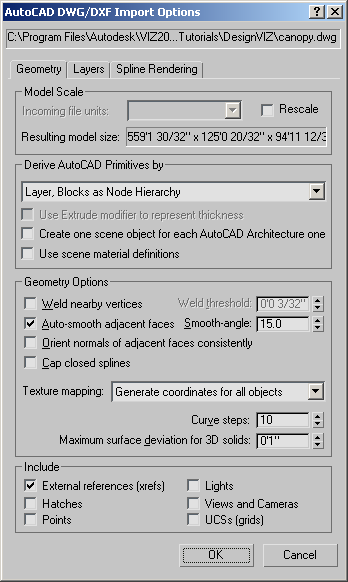
- Turn
on Rescale and set the Incoming File Units to Inches.
- Make
sure Derive AutoCAD Primitives By is set to Layer, Blocks As Node
Hierarchy, set Smooth-Angle to 15.0 if necessary,
and then click OK.
- Switch
to the Perspective viewport to a User viewport by pressing U.
-

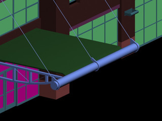
 Using
Zoom Region and Pan, zoom into the central part of the model until
you can clearly see the canopy overhanging the main doors.
Using
Zoom Region and Pan, zoom into the central part of the model until
you can clearly see the canopy overhanging the main doors.You might have to use Zoom Region a couple of
times and pan around a little.
- Choose
Rendering menu > Environment and turn off the Active switch in
the Exposure Control rollout.
If left on, the colors in the scene are over
saturated and appear to be self-illuminated.
-
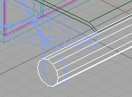
 On the main toolbar, click Quick
Render.
On the main toolbar, click Quick
Render.The cylindrical canopy element is segmented
rather than smooth, because the Smooth-angle value was too low during import.
- Press H to open the Select Objects dialog
and select the Layer:CanopyEnd object.
TipUse
the search field above the objects list.
- Delete
the Layer:CanopyEnd object.
- Import
the file again. Stop when the AutoCAD DWG/DXF Import Options dialog
opens.
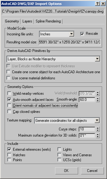
- On
the Geometry panel, turn on Rescale, set Incoming File Units to
Inches, and make sure Derive AutoCAD Primitives By is still set to
Layer, Blocks As Node Hierarchy. Set Smooth-Angle to 60.0 and
then click OK.
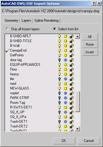
- Open
the Layers panel and activate Select From List.
- Click
the None button, scroll to the bottom of the list and then choose
the CanopyEnd layer. Click OK.
- Zoom
and Pan to the canopy and render the scene again.
Notice that the object looks much smoother.
- Right-click
the User viewport label and change it to Wireframe.
In this display mode, you can see that the Layer:CanopyEnd object
does not have much detail and relies upon smoothing groups to derive
its smoothness.
Adjust
smoothness with File Link:
This section will basically repeat the previous
section but incorporates the File Link Manager and also highlight
the Surface Deviation setting for 3D solids. Surface Deviation is
very useful when dealing with 3D objects that always seem to have
jagged edges when they're imported or linked to 3ds Max.
- Reset 3ds Max.
- From
the Customize menu, choose Units Setup, and then on the Units Setup
dialog choose Generic Units.
- Choose
File menu > File Link Manager.
Next you'll create a new preset to ensure that
File Link uses a Derive By setting that shows the object colors.
- On
the File Link Manager dialog, click the Presets tab.
- Click
the New button; this opens the New Settings Preset dialog. In the
New Name field enter Canopy and then click OK.
The Canopy preset appears in the list.
- Click
the Canopy preset and then click Modify.
This opens the File Link Settings dialog.
- Click
the Advanced tab and set the Derive AutoCAD Primitives By field
to Layers, Blocks as Node Hierarchy. Click Save.
This returns you to the File Link Manager dialog.
- Click
the File button and open canopy.dwg from
the \tutorials\designviz folder.
The file name and path appear in the File field.
- From
the Preset drop-down list, choose the Canopy preset.
- Turn
on Rescale, set the Incoming File Units to Inches, and then click
Attach This File.
- Switch
the Perspective viewport to a User viewport by pressing U.
-
Use
Zoom Region and Pan to zoom into the central part of the model so
you can see the canopy again.
- Choose
Rendering menu > Environment and make sure the Active switch
in the Exposure Control rollout is turned off.
-
On the main toolbar, click Quick
Render.
The cylindrical canopy element is segmented
again. When doing a File Link, you don't initially have control
over settings like smoothness unless you use a preset that's modified
to do so.
NoteIf
your cylinder is already smooth, it is most likely because you already
have a low surface deviation setting from a previous file link procedure.
- On
the File Link Manager dialog, click the Files tab.
- Make
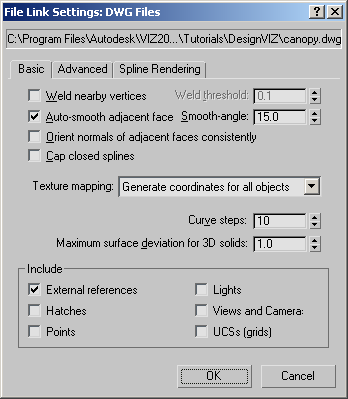
sure Show Reload Options is on and click the Reload button.
The File Link Settings: DWG Files dialog opens.
- On
the Basic panel, set Maximum Surface Deviation For 3D Solids to .05.
NoteLowering this value results in greater detail
in the geometry.
- Click
OK to reload the scene.
- Render
the scene again.
The object is reloaded and is smoother, as in
the previous exercise using the Smooth-Angle setting, but there
is a key difference that is most apparent when viewing the scene
in Wireframe mode.
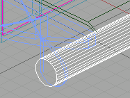
- Right-click
the User viewport label and choose Wireframe.
Notice how many segments make up the geometry
of Layer:CanopyEnd. The key benefit
to using the Surface Deviation setting for 3D Solid objects is the
amount of detail that comes across to 3ds Max. Geometry with
higher quantities of faces and surfaces are more refined which results
in a smoother model.
If detail is still missing, you can choose Reload
and further reduce the Surface Deviation setting.
- From
the Customize menu, choose Units Setup, and then on the Units Setup
dialog choose US Standard, and make sure the associated settings
are Feet w/Fractional Inches and 1/32.
Rescale
units and find missing maps:
The units used in the AutoCAD drawing must match
the units used in the 3ds Max scene. The scene can either adopt
the unit system used in the AutoCAD file, or objects can be rescaled
as they are imported into 3ds Max.
NotePhotometric lights in 3ds Max are, by
default, set to use international units as their unit scale. If
the objects are rescaled and photometric lights are used, you must
change the Lighting Units value in the Units Setup dialog to allow
for the proper inverse square falloff calculations.
- Reset 3ds Max and
choose File menu > Open. Set the Files Of Type to VIZ Render
(.drf) format.
- Browse
to the \tutorials\full_house folder and
open tut_living_room06.drf.
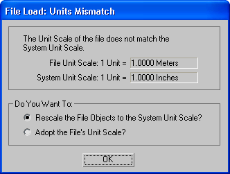
This is an Autodesk VIZ Render file created
with Architectural Desktop 2004 that causes the Units Mismatch dialog
to appear. The dialog indicates the DRF unit scale is in meters
while the 3ds Max unit scale is in inches.
- Choose
Rescale The File Objects to the System Unit Scale and then click
OK.
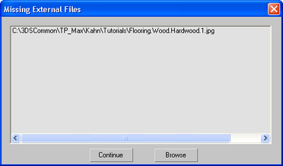
If you installed 3ds Max to a drive path
other than the default path, you may encounter the Missing External
Files dialog. The Missing External Files dialog appears and lists
missing map files that 3ds Max cannot locate. If the map files
are stored on your system, you will need to add their folder path
in the Configure External File Paths dialog when you click the Browse
button. If the files are not available, you will need to substitute
them from the Material Editor.
- Choose
Customize > Units Setup. Set the Lighting Units to American and
click OK.
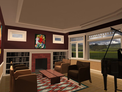
- Render
the scene.
Summary
In this tutorial, you learned about diagnosing
and fixing problems you might come across when working with 2D CAD
drawings and 3D models.