Create cross sections to show interior details of 3D objects.
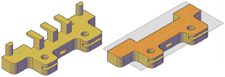
With the SECTIONPLANE command, you create a section object that acts as a cutting plane through solids, surfaces, meshes, or regions. Then turn on live sectioning to move the section object through the 3D model to reveal its inner details in real time.
You can align a section object using several methods.

 Show Me: Create and Rotate
a Section
Show Me: Create and Rotate
a SectionAlign the Section Plane to a 3D Face
One way to set the section plane is to click the face of an existing 3D object. (As you move the cursor, a dotted outline indicates the side of the plane to be selected.) The section plane is automatically aligned to the plane of the face you select.

Section object aligned to face
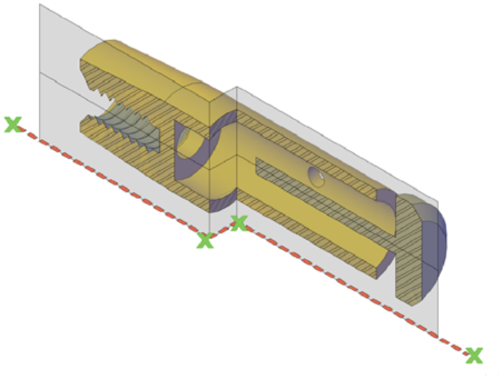
The section plane can be a straight line or it can have multiple or jogged sections. For example, a section containing a jog is one that cuts away a pie slice-shaped wedge from a cylinder.
Create a section line that has jogged segments by using the Draw Section option to pick multiple points throughout the 3D model.

Section object with jogged segment
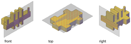
You can align section objects to a specified orthographic orientation of the current UCS, such as front, back, bottom, top, left, or right.

Orthographic section planes are placed so that they pass through the center of the 3D extents of all 3D objects in the drawing.
Create a Region to Represent the Cross Section
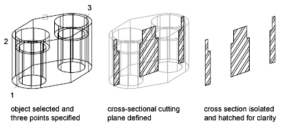
With the SECTION command, you can create a 2D region object that represents a planar cross section through a 3D solid object. You do not have live sectioning capabilities when you use this legacy method to create cross sections.

Define the plane of the cross section using one of the following methods:
The new region that represents the cross-sectional plane is placed on the current layer.