This describes the BSC slots. A backplane is positioned in the center of the BSC subrack. The BSC boards are installed on the front and rear sides of the backplane.
Figure 1 shows the physical structure of the BSC subrack. The cubes shown in the figure indicate boards.
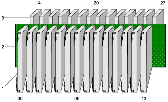
The backplane separates the BSC subrack into a front subrack and a rear subrack. The slots in the front subrack are numbered from 00 to 13 and the slots in the rear subrack are numbered from 14 to 27. The front subrack holds service boards and the rear subrack holds interface boards. In principle, each slot holds one board, but there are exceptions. Slots 20 and 21 hold one GOMU, and slots 22 and 23 hold one GOMU.
Two neighboring even and odd slots, for example, slot 00 and slot 01, slot 02 and slot 03, work in active/standby mode. The boards working in active/standby mode occupy the active and standby slots.