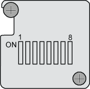
This describes the DIP switch on the BSC subrack. The DIP switch on the BSC subrack is used to define the numbering of the BSC subrack.
Appearance
Figure 1 shows the DIP switches on the BSC subrack.
Meaning of the DIP Bits
The DIP bits are numbered in ascending order from bit 1 to bit 8. ON represents digit 0 and OFF represents digit 1. Table 1 provides the definitions of the bits.
DIP Bit |
Meaning |
|---|---|
1 (the least significant bit) |
Subrack number setting bit |
2 |
Subrack number setting bit |
3 |
Subrack number setting bit |
4 |
Subrack number setting bit |
5 |
Subrack number setting bit |
6 |
Odd parity check bit |
7 |
Reserved, undefined, generally set to 0 (ON) |
8 (the most significant bit) |
|
If this bit is set to 0 (the status of the DIP bit is ON), the GSCU is set to Not Start Automatically. The startup of the GSCU depends on the GOMU. In other words, when the GSCU is started, it loads data from the GOMU.
If this bit is set to 1 (the status of the DIP bit is OFF), the GSCU is set to Start Automatically. When the GSCU is started, it checks whether the Flash file is valid. If the Flash file is valid, the GSCU loads data from the Flash. If the Flash file is invalid, the GSCU loads data from the GOMU.
Setting Scheme
Set DIP bits 1 through 5 and DIP bit 8.
Set DIP bit 7 to 0.
- Count the number of 1s that have been set.
If the number of 1s is even, set DIP bit 6 to 1.
If the number of 1s is odd, set DIP bit 6 to 0.
Assume that the subracks are numbered from 0 to 3. For the setting of the DIP switches in this case, refer to Table 2. Subrack 0 should be the GMPS. Subracks 1 to 3 may be the GEPS or the GTCS.
Subrack No. |
DIP Bit |
|||||||
|---|---|---|---|---|---|---|---|---|
| 1 | 2 | 3 | 4 | 5 | 6 | 7 | 8 | |
0 |
0 |
0 |
0 |
0 |
0 |
0 |
0 |
1 |
(ON) |
(ON) |
(ON) |
(ON) |
(ON) |
(ON) |
(ON) |
(OFF) |
|
1 |
1 |
0 |
0 |
0 |
0 |
0 |
0 |
0 |
(OFF) |
(ON) |
(ON) |
(ON) |
(ON) |
(ON) |
(ON) |
(ON) |
|
2 |
0 |
1 |
0 |
0 |
0 |
0 |
0 |
0 |
(ON) |
(OFF) |
(ON) |
(ON) |
(ON) |
(ON) |
(ON) |
(ON) |
|
3 |
1 |
1 |
0 |
0 |
0 |
1 |
0 |
0 |
(OFF) |
(OFF) |
(ON) |
(ON) |
(ON) |
(OFF) |
(ON) |
(ON) |
|
