This describes the principles of DFCU/DFCB configuration. Configuring the DFCU/DFCB is actually configuring the TRXs that require tuning in the DFCU or the DFCB, that is, configuring the connections of antennas and feeders. The configuration of the antenna feeder connections must be consistent with the physical cable connections on site.
Principles of Configuring the Antenna Feeder Connections in the DFCU
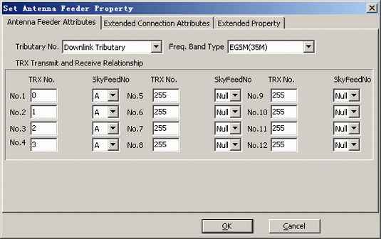
The DFCU has four cavities, which are used to perform the four-in-one function of TRXs. Configuring the antenna feeder connections is configuring the TRXs connected to the cavities. These TRXs are configured on tributary A among the downlink tributaries of antenna feeder connections. TRXs cannot be configured on tributary B.
One cavity of the DFCU can tune only one frequency. Interference occurs if frequencies are dense. The principles of the configuration of TRXs on tributary A are as follows:
- In the antenna feeder connections of the DFCU, up to four TRXs can be configured.
- In the antenna feeder connections of the DFCU, none of the TRXs can be configured with RF frequency hopping.
- In the antenna feeder connections of the DFCU, the Absolute Radio Frequency Channel Number (ARFCN) difference between two TRXs must be greater than or equal to 3.
- In the antenna feeder connections of the DFCU, the RF transmit mode of any TRX cannot be set to wideband combination. By default, the RF transmit mode is set to transmit independency.
- In the antenna feeder connections of the DFCU, if the RF transmit mode of a TRX is set to transmit diversity, see Principles of Configuring the DFCU/DFCB in Transmit Diversity Mode for details.
- When the DFCU uses six-in-one output mode, it must work with the DFCB. You need to configure the extension connections for the DFCU. For details on the configuration principles, see Principles of Configuring Extension Connections of the DFCU and Principles of Configuring the Antenna Feeder Connections of the DFCB.
- The DFCU should not be configured in slot 20 of the DAFU subrack in the BTS3012, BTS3012 II, or BTS3012AE. The slots on both sides of the DFCU slot should not be configured with the DFCU or the DFCB.
- The TRX to be tuned must be configured on downlink tributary A of the DFCU. Tributary B should not be configured with TRXs.
- The frequency band type of the DFCU must be the same as that of the TRX in the BTS.
Figure 1 shows the recommended configurations. TRXs 1, 2, 3, and 4 of an S4 cell are connected to DFCU 0.
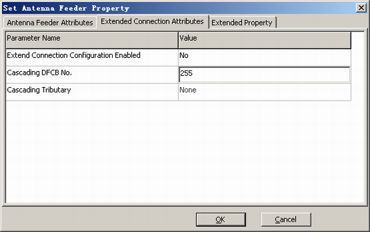
Principles of Configuring Extension Connections of the DFCU
The extension connections of the DFCU are configured to connect the two TRXs on tributary A or B of the DFCB to the DFCU to provide six-in-one output.
The principles of configuring the extension connections of the DFCU are as follows:
- The four TRXs connected to the DFCU and the two TRXs of the DFCB serve as one tuning unit. The ARFCN difference between any two TRXs among the six TRXs must be greater than or equal to 3.
- The configuration of the extension connections of the DFCU must be consistent with the physical connections. Otherwise, the tuning fails.
- The DFCB configured in the extension connections of the DFCU must exist physically.
- The DFCU cannot be bound to the QTRU.
Figure 2 shows the recommended configurations. Tributary A of DFCB 2 is connected to DFCU 0.
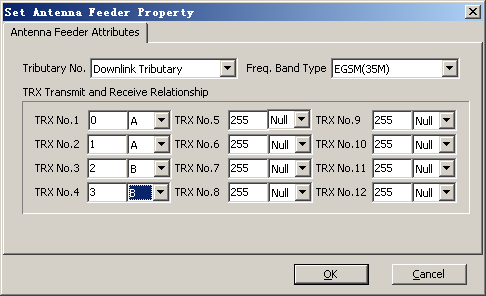
Principles of Configuring the Antenna Feeder Connections of the DFCB
The DFCB performs the TRX two-in-one output function. The antenna feeder connections are configured to connect the TRX to tributary A or B of the DFCB.
The principles of configuring the antenna feeder connections of the DFCB are as follows:
- The DFCB must cooperate with the DFCU to provide the six-in-one output of TRXs.
- In the antenna feeder connections of the DFCB, the TRX is connected to tributary A or B based on actual conditions.
- In the antenna feeder connections of the DFCB, tributary A or B can be configured with up to two TRXs.
- In the antenna feeder connections of the DFCB, the ARFCN difference between two TRXs on tributary A or B must be greater than or equal to 3. The ARFCN difference between a TRX on tributary A and another TRX on tributary B has no restriction. That is, the ARFCN of a TRX on tributary A can be the same as the ARFCN of another TRX on tributary B, because the two tributaries are independent of each other.
- In the antenna feeder connections of the DFCB, none of the TRXs can be configured with RF frequency hopping.
- In the antenna feeder connections of the DFCB, the RF transmit mode of any TRX cannot be set to wideband combination.
- In the antenna feeder connections of the DFCB, if the RF transmit mode of a TRX is set to transmit diversity, see Principles of Configuring the DFCU/DFCB in Transmit Diversity Mode for details.
- The DFCB does not require extension connections. The extension connections are configured on the DFCU.
- The DFCB should not be configured in slot 20 of the DAFU subrack in the BTS3012, BTS3012 II, or BTS3012AE. The slots on both sides of the DFCB slot should not be configured with the DFCU or the DFCB.
- The TRX to be tuned can be configured on downlink tributary A or B. Each tributary can be configured with up to two TRXs.
- The frequency band type of the DFCB must be the same as that of the TRX in the BTS.
In the following example, tributary A of the DFCB is set to TX1 and TX2 (input) and COM1 (output), and tributary B of the DFCB is set to TX3 and TX4 (input) and COM2 (output). TRU 0 and TRU 1 are connected to ports TX1 and TX2 on the DFCB respectively (tributary A). TRU 2 and TRU 3 are connected to ports TX3 and TX4 on the DFCB respectively (tributary B). Figure 3 shows the recommended configurations.
In the same group, the physical connections of the two TRXs are interchangeable, that is, the physical connections between the two TRUs (TRU0 and TRU 1) and the two ports (TX1 and TX2) are interchangeable, and the physical connections between the two TRUs (TRU 2 and TRU 3) and the two ports (TX3 and TX4) are interchangeable. When connecting cables, strictly follow the wiring diagram.
Principles of Configuring the DFCU/DFCB in Transmit Diversity Mode
If the RF transmit mode of a DTRU is transmit diversity, the main TRX and the diversity TRX have the same frequency. When the main TRX is configured in the antenna feeder connections of the DFCU/DFCB, the ARFCN difference between two TRXs must be greater than or equal to 3. To meet the requirement, you must adhere to the following configuration principles:
- The main TRX and the diversity TRX should not be configured on the same DFCU.
- The main TRX and the diversity TRX should not be configured on the same tributary of the DFCB.
- The main TRX and the diversity TRX should not be configured on the six-in-one output simultaneously, that is, the main carrier and the diversity carrier should not appear on the four TRXs of the DFCU and the two TRXs of the DFCB at the same time.
For example, TRU 0 is the diversity. The main TRX is configured on DFCU 0. The diversity TRX is configured on tributary B of DFCB 2. Tributary A of DFCB 2 is in cascaded connection with DFCU 0 to provide six-in-one output.