This describes how to configure the M3UA entities. You need to configure the M3UA entities to achieve A over IP or to enable communication between BSCs. The local entity and destination entity must be configured. If there is no direct physical link between the local entity and the destination entity, you need to configure a signaling transfer entity.
| Scenario | BSC initial configuration and BSC capacity expansion |
| Mandatory/Optional | Mandatory |
- The local entity must be configured before the destination entity is configured.
- The local entity and destination entity must be configured before the signaling transfer entity is configured.
- The name and code of each entity must be unique.
Prerequisite
None.
Preparation
Parameter |
Example |
Source |
|---|---|---|
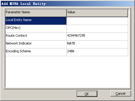
Local Entity Name |
BSC001 |
BSC internal planning |
OPC (Hex) |
B1 |
Network planning |
Route Context |
4294967295 |
Negotiation with the peer |
Encoding Scheme |
14 bits |
Network planning |
Network Indicator |
Reserved for domestic use |
Network planning |
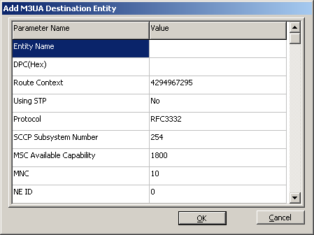
Destination Entity Name |
MSC001 |
BSC internal planning |
DPC(Hex) |
D1 |
Network planning |
Using STP |
Yes |
Network planning |
Protocol |
RFC3332 |
Negotiation with the peer |
Procedure
- Configure the M3UA local entity.
- Configure the M3UA destination entity.
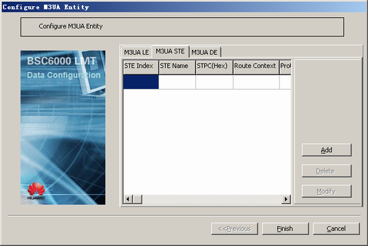
- In the dialog box shown in Figure 1, click the M3UA DE tab to display the tab page, as shown in Figure 3.
- Click Add. A dialog box is displayed, as shown in Figure 4.
 NOTE:
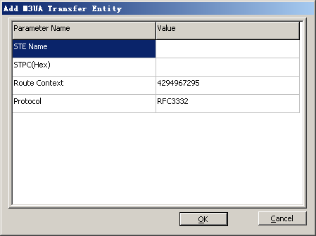
NOTE: If there is no direct physical link between the local entity and the destination entity, you need to configure a signaling transfer entity. In the dialog box shown in Figure 4, set Using STP to Yes.
Route Contextis mapped to a destination entity/signaling transfer entity. Except the invalid value 4294967295, the Route Context of a destination entity or a signaling transfer entity must be unique. Otherwise, the configuration is invalid.
To achieve A over IP, SCCP Sub-System No. is set to 254; to enable communication between BSCs, SCCP Sub-System No. is set to 143.
- Check whether there is a direct physical link between the local entity and the destination entity.
If...
Then...
There is a direct physical link between the local entity and the destination entity,
The task is complete.
There is no direct physical link between the local entity and the destination entity,
Go to 4.
- Configure the M3UA transfer entity.