This describes how to configure a BTS3900E GSM in O6 mode on the BSC side.
| Scenario | Initial data configuration of a new BTS |
| Mandatory/Optional | Optional |
| NEs Involved | BTS3900E GSM |
- A single BTS3900E module can be configured with one BTS3900E O6 site and does not require the support of other board modules.
- Both the E1 transmission mode and the FE transmission mode are supported but only one mode can be selected.
- BTS cascading is not supported in FE transmission mode.
- The configuration methods for the AC type and the DC type are the same.
Prerequisites
- The BSC global data, BSC devices, BSC links, and BSC clock are configured.
- The GEIUB/GOIUB is configured. In addition, there are idle ports.
- The GXPUM is configured for the GMPS/GEPS where the GEIUB/GOIUB is located.
Preparation
Parameter |
Example |
Source |
|
|---|---|---|---|
Site attributes |
Site Name |
BTS 1 |
Network planning |
Site Type |
BTS3900E GSM |
Network planning |
|
Upper-Level Port No. |
0 GEIUB Port |
Network planning |
|
Multiplexing Mode |
4:1 |
Network planning |
|
FlexAbis Mode |
Fix Abis |
Network planning |
|
Service Mode |
TDM |
Network planning |
|
Active |
Deselected |
Network planning |
|
Config Ring |
No |
Network planning |
|
Config AbisByPass |
No |
Network planning |
|
Cell attributes |
Number of Cells |
1 |
Network planning |
Cell Name |
Cell 1-0 |
Network planning |
|
Frequency Band |
GSM900 |
Network planning |
|
MCC |
460 |
Network planning |
|
MNC |
01 |
Network planning |
|
LAC |
8240 |
Network planning |
|
CI |
1, 2, 3 |
Network planning |
|
BCC |
1 |
Network planning |
|
NCC |
1 |
Network planning |
|
Cell Extension Type |
Common cell |
Network planning |
|
Cell Type |
Common cell |
Network planning |
|
TRX attributes |
RXU Name of BTS3900E |
BTS3900E0 |
BTS internal planning |
Send Receive Mode |
Single Feeder (1TX + 1RX) |
BTS internal planning |
|
Assigned Cell |
Cell 1-0 |
Network planning |
|
Frequency configuration |
57 (main BCCH frequency), 68, 75, 87, 93, 102 |
Network planning |
|
TRX configuration |
TRX0, TRX1, TRX2, TRX3, TRX4, and TRX5 |
Network planning |
|
FH Mode |
None |
Network planning |
|
Procedure
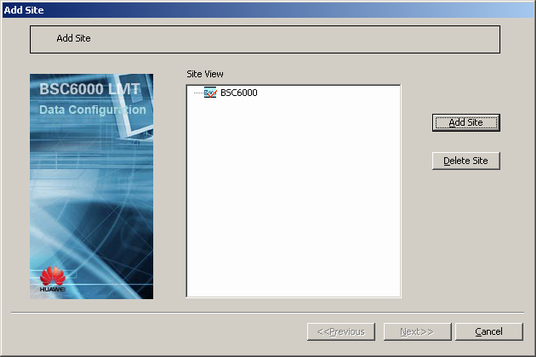
- On the BSC6000 Local Maintenance Terminal, right-click the GEIUB/GOIUB interface board in the GMPS/GEPS and choose Add Site from the shortcut menu. A dialog box is displayed, as shown in Figure 1.
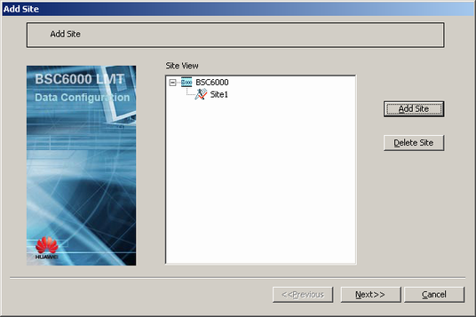
- Click Add Site. A dialog box is displayed, as shown in Figure 2.
- Set the parameters by referring to Table 1.
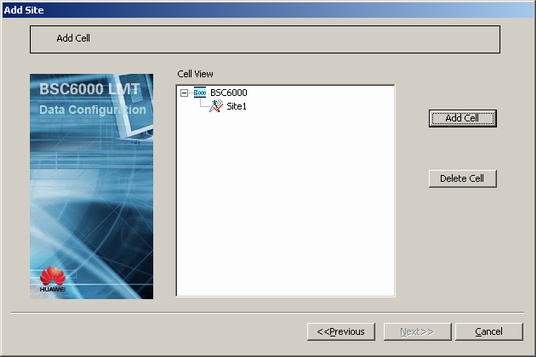
- Click OK. A dialog box is displayed, as shown in Figure 3.
- Click Next. A dialog box is displayed, as shown in Figure 4.
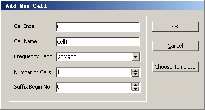
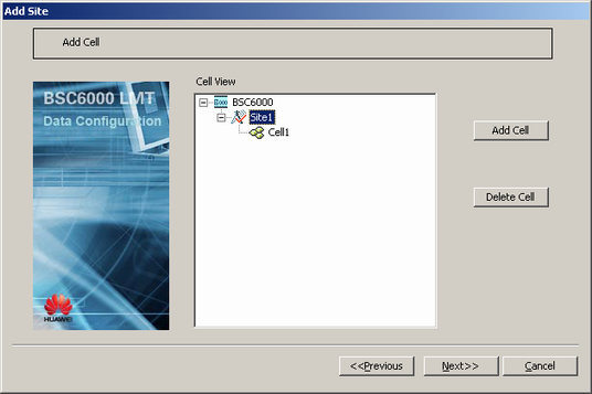
- Select a BTS, and then click Add Cell. A dialog box is displayed, as shown in Figure 5.
- Set the parameters by referring to Table 1.
- Click OK. A dialog box is displayed, as shown in Figure 6.
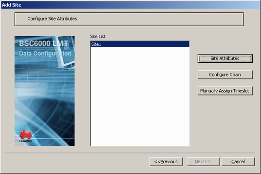
- Click Next. A dialog box is displayed, as shown in Figure 7.
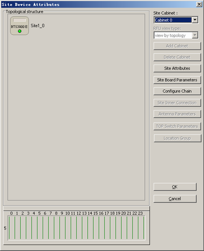
- Click Site Attributes. A dialog box is displayed, as shown in Figure 8.
- Configure the modules of the BTS3900E.
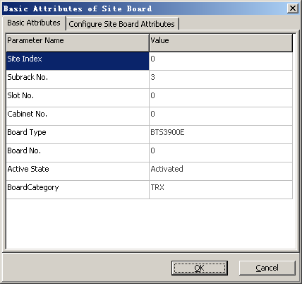
- Right-click the BTS3900E, and then choose from the shortcut menu. A dialog box is displayed, as shown in Figure 9.
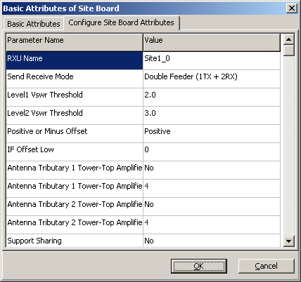
- Click the Configure Site Board Attributes tab to display the tab page, as shown in Figure 10.
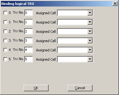
- Right-click the BTS3900E, and then choose from the shortcut menu. A dialog box is displayed, as shown in Figure 11.
- Select six TRXs and the cells allocated to them, and set TRX numbers according to the data provided by the network planning department.
 NOTE:
NOTE: In BTS3900E O6 configuration, one BTS3900E maps one cell. Therefore, the six logical TRXs that are bound to one BTS3900E belong to the same allocated cell.
- In the Site Device Attributes dialog box, add other modules. For details, see Adding BTS Modules.
- Click OK to return to the dialog box, as shown in Figure 7.
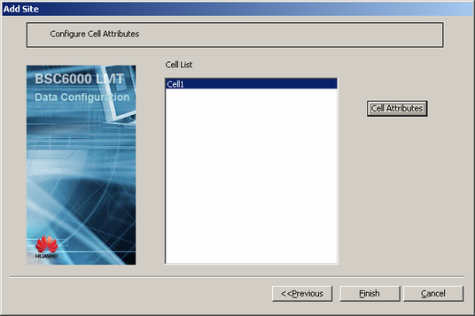
- Click Next. A dialog box is displayed, as shown in Figure 12.
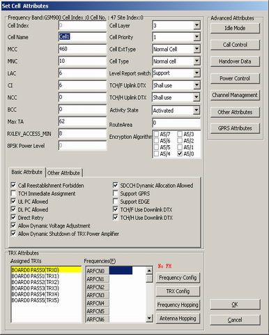
- Select the added cell, and then click Cell Attributes. A dialog box is displayed, as shown in Figure 13.
NOTE:
- For two cells, the values of at least one of the following parameters should be different: MCC, MNC, LAC, and CI.
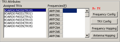
- In the TRX Attributes group box, select the allocated TRXs, as shown in Figure 14.
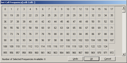
- Click Frequency Config. A dialog box is displayed, as shown in Figure 15. Then, select a frequency.
- Click OK to return to the dialog box, as shown in Figure 13.
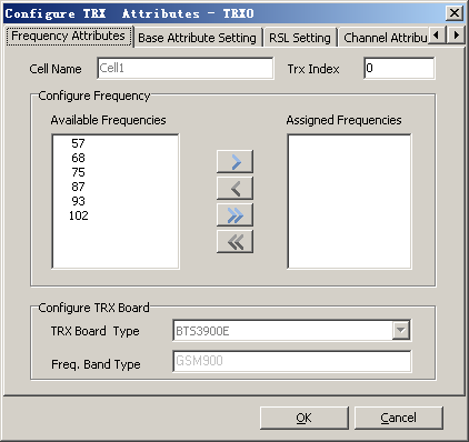
- Click TRX Config. A dialog box is displayed, as shown in Figure 16.
- Move a frequency corresponding to the TRX from Available Frequencies to Assigned Frequencies.
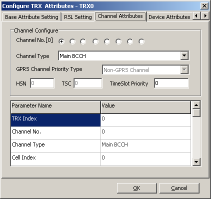
- Click the Channel Attributes tab. A tab page is displayed, as shown in Figure 17. Then, set the channel types corresponding to eight channel numbers.
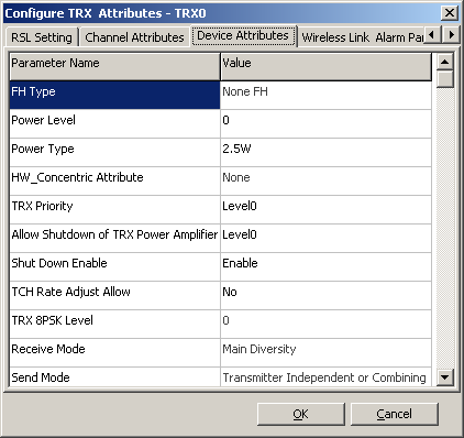
- Click the Device Attributes tab. A dialog box is displayed, as shown in Figure 18.
- Set site device attribute parameters.
- Click OK to return to the dialog box, as shown in Figure 13.
- Repeat 19 through 24 until the frequencies, channel attributes, and device attributes of all the TRXs in a cell are configured.
- Click OK to return to the dialog box, as shown in Figure 12.
- Click Finish. The configuration of the BTS is complete.
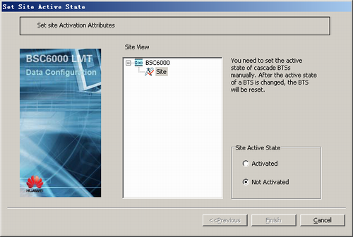
- Activating a BTS.
- On the Management Tree tab page of the BSC6000 Local Maintenance Terminal, right-click the target BTS and choose from the shortcut menu. A dialog box is displayed, as shown in Figure 19.