This describes how to add a DBS3900 GSM in S2/2/2 mode for the BSC and configure its attributes, logical TRXs, and cell attributes.
| Scenario | Initial configuration of a new BTS |
| Mandatory/Optional | Mandatory |
| NEs Involved | DBS3900 GSM |
- For the parameters not mentioned in this section, retain the default values during the initial configuration.
- Abis interface boards are classified into the GEIUB, GOIUB, GEHUB, GFGUB, and GOGUB.
Prerequisites
- The data described in Data to Be Negotiated and Planned for DBS3900 Initial Configuration is already obtained.
- The BSC global data, BSC devices, BSC links, and BSC clock are configured.
- The GEIUB/GOIUB is configured. In addition, there are idle ports.
- The GXPUM is configured for the GMPS/GEPS where the GEIUB/GOIUB is located.
Preparation
Figure 1 shows the typical RF cable connection of the DBS3900 GSM in S2/2/2 mode.
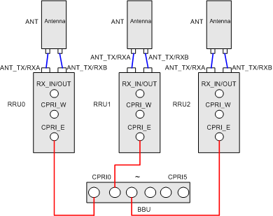
The corresponding BTS parameters are described in Table 1.
Parameter |
Parameter Value |
|
|---|---|---|
Active |
Deselected |
|
Ring Mode |
No |
|
Number of Cells |
3 |
|
Number of RXU Chains |
3 |
|
Cable connection of the BBU and RRU |
Star Topology |
|
Number of DRRUs |
3 |
|
Chain Type |
Chain |
|
Chain No. and Chain Head Board Port of RRU0 |
Chain No. |
0 |
Chain Head Board Port |
0 |
|
Chain No. and Chain Head Board Port of RRU1 |
Chain No. |
1 |
Chain Head Board Port |
1 |
|
Chain No. and Chain Head Board Port of RRU2 |
Chain No. |
2 |
Chain Head Board Port |
2 |
|
TX/RX mode in the DRRU board attributes |
Double Feeder (2TX + 2RX) |
|
RF RX/TX mode |
Receive Mode |
Main Diversity |
Send Mode |
No Combining |
|
Power Type |
15W |
|
TMA |
None |
|
Frequency Hopping |
None |
|
Procedure
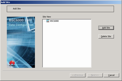
- On the BSC6000 Local Maintenance Terminal, right-click the GEIUB interface board of the GMPS or GEPS, and then choose Add Site from the shortcut menu. A dialog box is displayed, as shown in Figure 2.
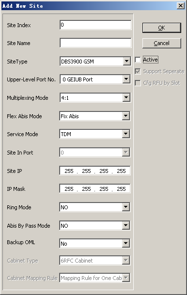
- Click Add Site. A dialog box is displayed, as shown in Figure 3.
- Set Site Type to DBS3900 GSM, Ring Mode to NO, and set other parameters listed in Table 2.
- Click OK. A dialog box is displayed, as shown in Figure 4.
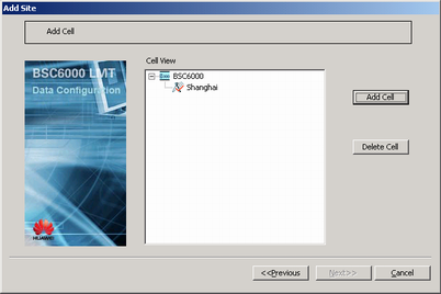
- Click Next. A dialog box is displayed, as shown in Figure 5.
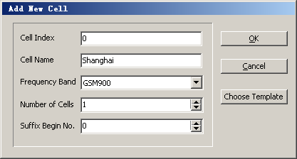
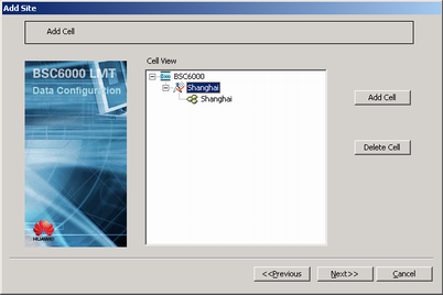
- Select a BTS, and then click Add Cell. A dialog box is displayed, as shown in Figure 6.
- Set Number of Cells to 3, and set other parameters.
 CAUTION:
 If the frequency band is not configured correctly, you must delete the configured cell or BTS and then add a cell or BTS for modifying the frequency band. The reason is that a frequency band cannot be modified in a configured cell or BTS.
- Click OK. A dialog box is displayed, as shown in Figure 7.
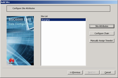
- Click Next. A dialog box is displayed, as shown in Figure 8.
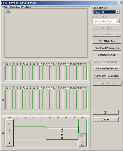
- Click Site Attributes. A dialog box is displayed, as shown in Figure 9.
- Configure the RXU chain and DRRU.
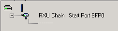
- In the Site Device Attributes dialog box, right-click
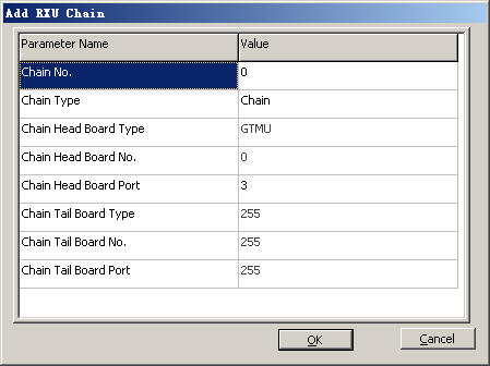
 and choose from the shortcut menu. A dialog box is displayed, as shown in Figure 10.
- Click OK. The RXU chain is added successfully, as shown in Figure 11.
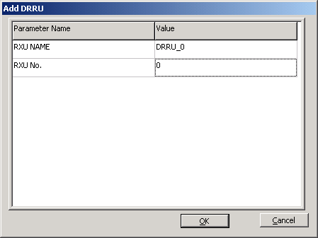
- Right-click the RXU chain, and then choose . A dialog box is displayed, as shown in Figure 12.
- Set RXU NAME and RXU No..
 NOTE:
NOTE: RXU NAME of different DRRUs under the same BTS must be unique. Otherwise, the system may display error information.
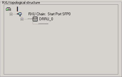
- Click OK. The DRRU chain is added, as shown in Figure 13.
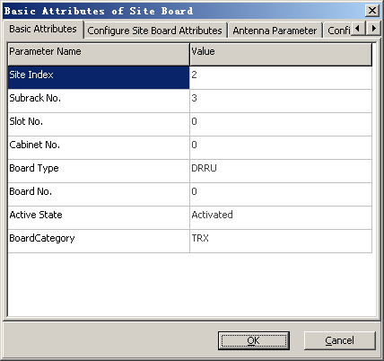
- Right-click the DRRU, and then choose . A dialog box is displayed, as shown in Figure 14.
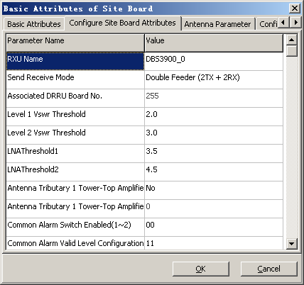
- Click the Configure Site Board Attributes tab to display the tab page, as shown in Figure 15.
- Set Send Receive Mode to Double Feeder (2TX + 2RX). NOTE:
When two TRXs are bound in the DRRU and the required power type is 30 W, 25 W, or 12 W, the RX/TX mode of the DRRU must be set to Double Feeder (2TX + 2RX) or Double Feeder (2TX + 4RX).
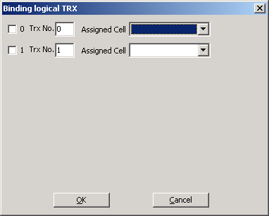
- Right-click the DRRU, and then choose from the shortcut menu. A dialog box is displayed, as shown in Figure 16.
- Select two TRXs and the cells allocated to them, and set TRX numbers according to the data provided by the network planning department. NOTE:
When the DBS3900 is in S2/2/2 mode, one DRRU corresponds to one cell. Therefore, the two logical TRXs that are bound to one DRRU belong to the same allocated cell.
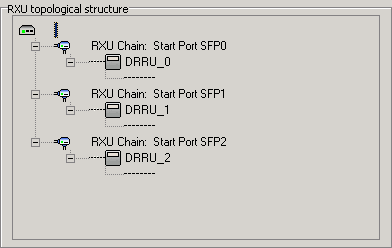
- Repeat 11.a through 11.m to configure the other two RXU chains and the DRRU under this chain. The final configuration result is shown in Figure 17.
- In the Site Device Attributes dialog box, right-click
- Add other modules to subrack 2 in the Site Device Attributes dialog box. For details, see Adding BTS Modules.
- Click OK to return to the dialog box, as shown in Figure 8.
- Click Next. A dialog box is displayed, as shown in Figure 18.
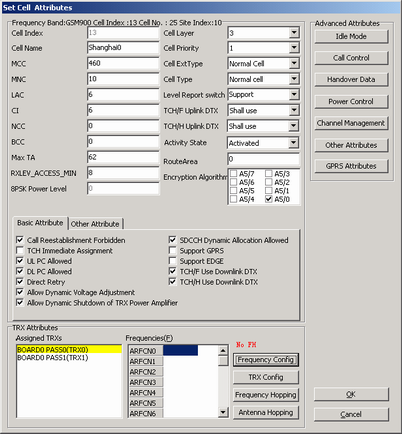
- Select the added cell, and then click Cell Attributes. A dialog box is displayed, as shown in Figure 19.
NOTE:
- For two cells, the values of at least one of the following parameters should be different: MCC, MNC, LAC, and CI.
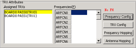
- In the TRX Attributes group box, select the allocated TRXs, as shown in Figure 20.
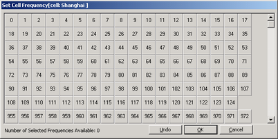
- Click Frequency Config. A dialog box is displayed, as shown in Figure 21. Then, select a frequency.
- Click OK to return to the dialog box, as shown in Figure 19.
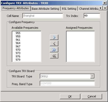
- Click TRX Config. A dialog box is displayed, as shown in Figure 22.
- Move a frequency corresponding to the TRX from Available Frequencies to Assigned Frequencies.
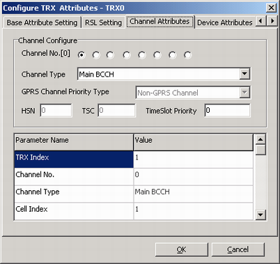
- Click the Channel Attributes tab. A tab page is displayed, as shown in Figure 23. Then, set the channel types corresponding to the channel numbers.
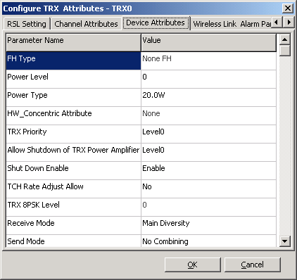
- Click the Device Attributes tab. A dialog box is displayed, as shown in Figure 24.
- Set Power Type, Send Mode, and Receive Mode according to Table 1. NOTE:
- The power types that can be configured for the DRRU are 12 W, 15 W, 25 W, and 30 W.
- When two logical TRXs are bound in the DRRU, the power of each logical TRX can only be set to "15W". Otherwise, the system may display error information.
- When Send Mode is set to "Transmitter Independent or Combining", the system determines whether to apply send mode "Transmitter Independent" or "Combining" according to the receive and send modes of the antenna and the binding logical TRX.
- Click OK to return to the dialog box, as shown in Figure 19.
- Repeat 19 through 24 until the frequencies of all the TRXs, channel attributes, and device attributes in a cell are configured.
- Click OK to return to the dialog box, as shown in Figure 18.
- Repeat 15 through 26 until the attributes of all the cells are configured.
- Click Finish. The configuration of the BTS is complete.
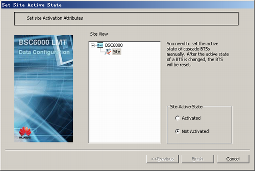
- Activating a BTS.
- On the Management Tree tab page of the BSC6000 Local Maintenance Terminal, right-click the target BTS and choose from the shortcut menu. A dialog box is displayed, as shown in Figure 25.