This describes how to add the RXU chain and RF module when the BBU and the RF module are connected in a ring topology.
| Mandatory/Optional | Mandatory |
| NEs Involved | BTS3900 GSM, BTS3900 GSM/UMTS, BTS3900A GSM, BTS3900A GSM/UMTS |
Prerequisite
- When star and chain topologies are applied for the BBU and the RF module, each ring supports three-level cascading of the RF module.
- With different settings of Cabinet Mapping Rule, both the location of the DRFU/GRFU/MRFU and the value of Hop set for the RXU chain are different. For details, see Mapping Rule of the RFU Cabinet.
- According to the cabinet mapping rule, Mapping Rule for Two Cabinets should be configured for the two-level cascading of the RXU chain.
- According to the cabinet mapping rule, Mapping Rule for Three Cabinets should be configured for the three-level cascading of the RXU chain.
Preparation
Site Type |
Working Standard |
RF Module Type |
Number of TRXs Supported by Each Module |
|
|---|---|---|---|---|
Physical |
Logical |
|||
DBS3900 |
GSM |
An RRU module in the RRU3004 |
DRRU |
1-2 |
RRU3008 |
GRRU |
1-8 |
||
GSM + UMTS |
RRU3908 |
MRRU |
1-6 |
|
BTS3900, BTS3900A |
GSM |
DRFU |
DRFU |
1-2 |
GRFU |
GRFU |
1-6 |
||
GSM + UMTS |
MRFU |
MRFU |
1-6 |
|
Procedure
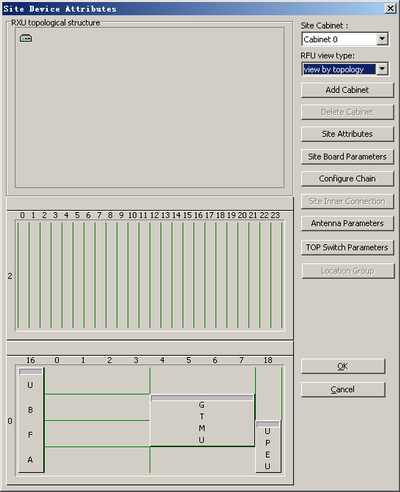
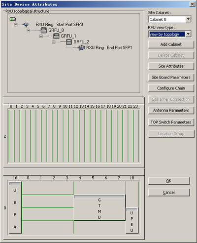
- On the right side of the Site Device Attributes dialog box, set RFU view type to View by topology. The result of the configuration in star topology is shown in Figure 2.
- In the Site Device Attributes dialog box, right-click
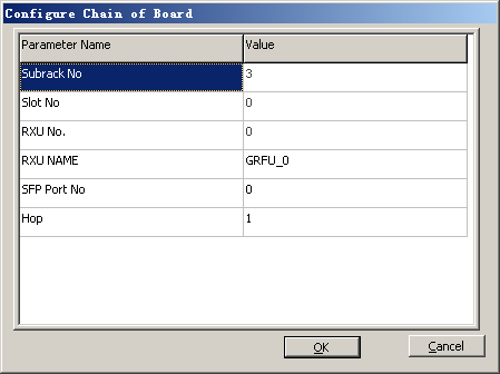
 and choose from the shortcut menu. A dialog box is displayed, as shown in Figure 3.
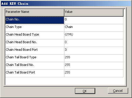
- Set Chain Type to Ring, and set Chain Head Board Port and Chain Tail Board Port.
 CAUTION:
 - "Chain Head Board Port" and Chain Tail Board Port must be consistent with the number of the CPRI port connected to the GTMU.
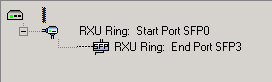
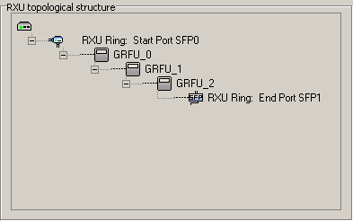
- Click OK. The RXU chain is added successfully, as shown in Figure 4.
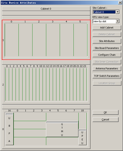
- On the right side of the Site Device Attributes dialog box, set RFU view type to View by slot.
- In the Site Device Attributes dialog box, right-click the corresponding slot as described in Figure 5, and choose . A shortcut menu is displayed, as shown in Figure 6.
- Set RXU NAME, SFP Port No., and Hop. Click OK. The GRFU is added. CAUTION:
- In ring topology, SFP Port No. of each GRFU module must be consistent with "Chain Head Board Port" of the RXU chain.
- Hop indicates the grade of the RXU chain that is carried on the board. In chain topology, the grades of each GRFU board are 1, 2, and 3.
- In physical connections, the CPRI_W port of the RRU indicates the signal input, and the CPRI_E port indicates the signal output. The CPRI_1 port of the DRFU indicates the signal input, and the CPRI_0 port indicates the signal output.
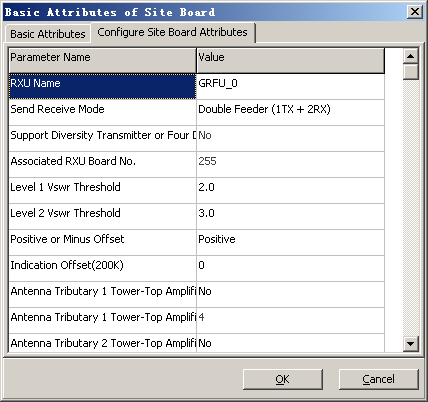
- Right-click the GRFU and then choose from the shortcut menu. In the displayed dialog box, click the Configure Site Board Attributes tab to set
related parameters, as shown in Figure 7.
 NOTE:
NOTE: - When the DRRU is applied, Associated DRRU Board No. is displayed in the dialog box.
- When the GRRU or MRRU is applied, Associated RXU Board No. is displayed in the dialog box.
- When the DRFU is applied, Associated DRFU Board No. is displayed in the dialog box.
- When the GRFU or MRFU is applied, Associated RXU Board No. is displayed in the dialog box. In addition, Support Diversity Transmitter or Four Diversity Receiver is added.
- Set the parameters by referring to Table 2.
Table 2 Description of setting board attributes of the BTS Parameter
Setting Description
Send Receive Mode
Set this parameter according to the actual RF connections. For details, see Setting Antenna Attributes.
- The DRRU, GRRU, and MRRU support the following TX/RX modes: Single Feeder (1TX + 1RX), Single Feeder (1TX + 2RX), Double Feeder (2TX + 2RX), Double Feeder (2TX + 4RX), Double Feeder (1TX + 1RX), and Double Feeder (1TX + 2RX).
- The DRFU supports the following TX/RX modes: Single Feeder (1TX + 1RX), Single Feeder (1TX + 2RX), Double Feeder (2TX + 2RX), Double Feeder (2TX + 4RX), Double Feeder (1TX + 1RX), and Double Feeder (1TX + 2RX).
- The GRFU and MRFU support the following TX/RX modes: Single Feeder (1TX + 1RX), Single Feeder (1TX + 2RX), Double Feeder (2TX + 2RX), Double Feeder (2TX + 4RX), Double Feeder (1TX + 1RX), and Double Feeder (1TX + 2RX).
Support Diversity Transmitter or Four Diversity Receiver
- When the GRFU or MRFU is added, this parameter is displayed.
- When Send Receive Mode of the GRFU or MRFU is set to Double Feeder (2TX + 4RX), Associated RXU Board No. can be configured only when you set this parameter to Yes.
Associated DRRU Board No. or Associated RXU Board No.
- You need to set this parameter when Send Receive Mode of the DRRU is set to Single Feeder (1TX + 2RX) or Double Feeder (2TX + 4RX).
- You need to set this parameter when Send Receive Mode of the MRRU and the GRRU is set to Double Feeder (2TX + 4RX).
- You need to set this parameter when Send Receive Mode of the GRFU and the MRFU is set to Double Feeder (2TX + 4RX).
- The value of this parameter must be consistent with that set in the "Basic Attributes of Site Board" dialog box for the corresponding board.
Antenna Tributary 1 Tower-Top Amplifier Flag and Antenna Tributary 2 Tower-Top Amplifier Flag
Set this parameter according to the actual configuration of the antenna.
Antenna Tributary 1 Tower-Top Amplifier Attenuation Factor(dB) and Antenna Tributary 2 Tower-Top Amplifier Attenuation Factor(dB)
Set this parameter to TMA Gain-4. Obtain information on the "TMA gain" from the product specifications.
NOTE: - You need not set Associated DRFU Board No. in any TX/RX mode.
- The prerequisite for configuration of Associated DRRU Board No. or Associated RXU Board No. is that the associated RF module is configured and that the RF module does not have any association with other boards.
- Click OK to return to the Site Device Attributes dialog box.
- Right-click the GRRU, and then choose from the shortcut menu. A dialog box is displayed, as shown in Figure 8.
NOTE:
- Different logical TRXs on the same board can be configured to different cells.
- If the DRRU, DRFU, GRFU, or MRFU is added, you need not select transmit channel A or B in the Binding logical TRX dialog box.
- Select the required TRXs and the cells allocated to them, and set TRX numbers.
- Click OK to return to the Site Device Attributes dialog box.
- Repeat 6 through 13 to configure other RXU chains and RF modules.
- On the right side of the Site Device Attributes dialog box, set RFU view type to View by topology. The result of the configuration in star topology is shown in Figure 9.