This describes how to add a BTS3900 GSM in S4/4/4 mode for the BSC and configure its attributes, logical TRXs, and cell attributes.
| Scenario | Initial configuration of a new BTS |
| Mandatory/Optional | Mandatory |
| NEs Involved | BTS3900 GSM |
- For the parameters not mentioned in this section, retain the default values during the initial configuration.
- Abis interface boards are classified into the GEIUB, GOIUB, GEHUB, GFGUB, and GOGUB.
Prerequisites
- The BSC global data, BSC devices, BSC links, and BSC clock are configured.
- The GEIUB/GOIUB is configured. In addition, there are idle ports.
- The GXPUM is configured for the GMPS/GEPS where the GEIUB/GOIUB is located.
Preparation
The corresponding BTS parameters are described in Table 1.
Parameter |
Example |
Data Source |
|
|---|---|---|---|
Site Configuration |
S4/4/4 |
Network planning |
|
BTS attributes |
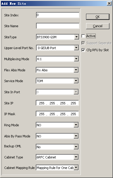
Site Name |
Shanghai |
Network planning |
Site Index |
0 |
||
Site Type |
BTS3900 GSM |
||
Multiplexing Mode |
4:1 |
||
Upper-Level Port No. |
0 GEIUB Port |
||
FlexAbis Mode |
Fix Abis |
||
Service Mode |
TDM |
||
Active |
Deselected |
||
Board attributes |
RXU NAME |
GRFU_0, GRFU_1, GRFU_2 |
Network planning |
SFP Port No. |
0, 1, 2 |
||
Send Receive Mode |
Single Antenna Double Receiver |
||
Antenna Tributary 1 Tower-Top Amplifier Flag |
No |
||
Antenna Tributary 1 Tower-Top Amplifier Attenuation Factor (dB) |
0 |
||
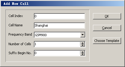
Cell attributes |
Cell Index |
0, 1, 2 |
Network planning |
Cell Name |
Shanghai_0, Shanghai_1, Shanghai_2 |
||
Frequency Band |
GSM900 |
||
MCC |
460 |
||
MNC |
01 |
||
LAC |
8240 |
||
CI |
2 |
||
NCC |
1 |
||
BCC |
1 |
||
Cell Layer |
1 |
||
Encryption Algorithm |
A5/0 |
||
Support GPRS |
Yes |
Negotiation with the peer end |
|
Support EDGE |
No |
||
TRX attributes |
Frequencies (F) |
955, 958, 961, 964, 967, 970, 973, 976, 979, 982, 985, 988 |
Network planning |
Receive Mode |
Main Diversity |
||
Send Mode |
Transmitter Independent or Combining |
||
Procedure
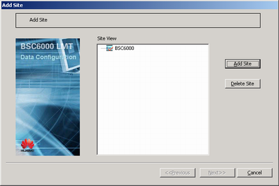
- On the BSC6000 Local Maintenance Terminal, right-click the GEIUB interface board of the GMPS or GEPS, and then choose Add Site from the shortcut menu. A dialog box is displayed, as shown in Figure 1.
- Click Add Site. A dialog box is displayed, as shown in Figure 2. Then, set parameters in the displayed dialog box.
- Click OK. A dialog box is displayed, as shown in Figure 3.
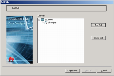
- Click Next. A dialog box is displayed, as shown in Figure 4.
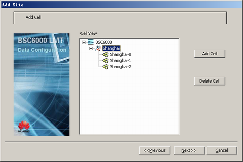
- Select the target BTS and click Add Cell. A dialog box is displayed, as shown in Figure 5. Then, set parameters in the displayed dialog box.
 CAUTION:
 If you find the configuration error of a frequency band in a cell or BTS after the configuration is complete, you need to delete the cell or BTS and then add a cell or BTS for modifying a frequency band. The reason is that a frequency band cannot be modified in a configured cell or BTS.
- Click OK. A dialog box is displayed, as shown in Figure 6.
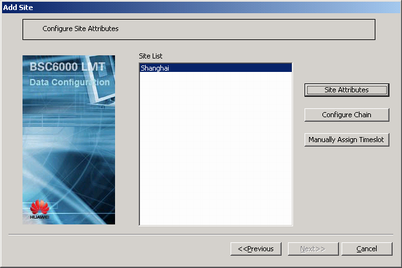
- Click Next. A dialog box is displayed, as shown in Figure 7.
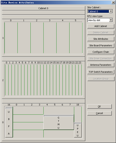
- Click Site Attributes. A dialog box is displayed, as shown in Figure 8.
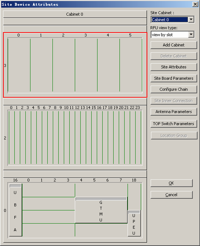
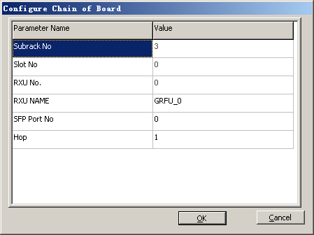
- In the Site Device Attributes dialog box, right-click the corresponding slot as described in Figure 9, and choose . A shortcut menu is displayed, as shown in Figure 10.
- Set RXU NAME, SFP Port No., and Hop. Click OK. The GRFU is added.
 NOTE:
NOTE: - SFP Port No. must be consistent with the CPRI ports connected to the GTMU.
- Hop indicates the grade of the RXU chain that is carried on the board.
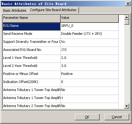
- Right-click the GRFU and then choose from the shortcut menu. In the displayed dialog box, click the Configure Site Board Attributes tab, as shown in Figure 11. Then, set related parameters.
- Click OK to return to the Site Device Attributes dialog box.
- Right-click the GRFU, and then choose from the shortcut menu. A dialog box is displayed, as shown in Figure 12.
- Select the required TRXs and the cells allocated to them, and set TRX numbers.
- Click OK to return to the Site Device Attributes dialog box.
- Repeat 9 through 15 to configure multiple RF modules and other logical TRXs.
- Add other modules to subrack 2 in the Site Device Attributes dialog box. For details, see Adding BTS Modules.
- Click OK to return to the dialog box, as shown in Figure 7.
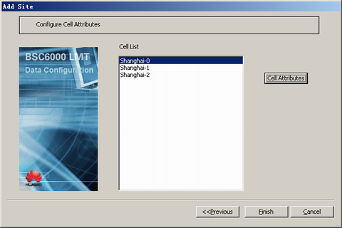
- Click Next. A dialog box is displayed, as shown in Figure 13.
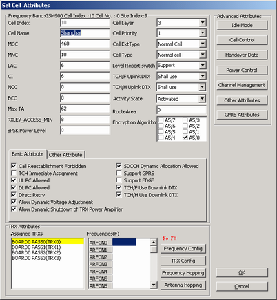
- Select the added cell, and then click Cell Attributes. A dialog box is displayed, as shown in Figure 14.
- Set parameters of basic cell attributes. NOTE:
For two cells, the values of at least one of the following parameters should be different: MCC, MNC, LAC, and CI.
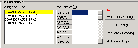
- In the TRX Attributes group box, select the allocated TRXs, as shown in Figure 15.
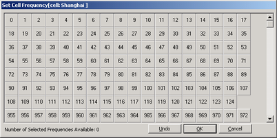
- Click Frequency Config. A dialog box is displayed, as shown in Figure 16. Then, select a frequency.
- Click OK to return to the Set Cell Attributes dialog box.
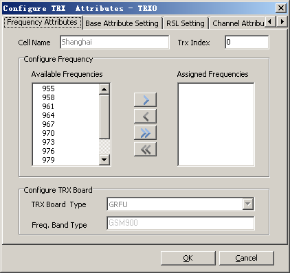
- Click TRX Config. A dialog box is displayed, as shown in Figure 17.
- Add a frequency corresponding to the TRX from Available Frequencies to Assigned Frequencies.
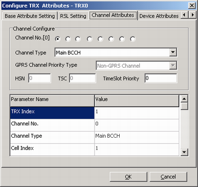
- Click the Channel Attributes tab. A tab page is displayed, as shown in Figure 18. Then, set the channel types corresponding to eight channel numbers.
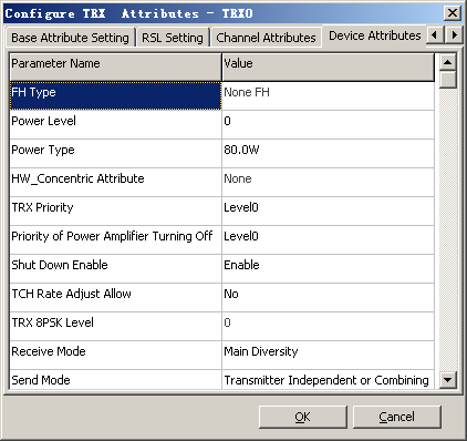
- Click the Device Attributes tab. A dialog box is displayed, as shown in Figure 19.
- Set Power Level, Power Type, Receive Mode, and Send Mode.
- Click OK to return to the Set Cell Attributes dialog box.
- Repeat 25 through 30 until the frequencies of all the TRXs, channel attributes, and device attributes in a cell are configured.
- Click OK to return to the Add Site dialog box.
- Repeat 20 through 32 until the attributes of all the cells are configured.
- Click Finish. The configuration of the BTS is complete.
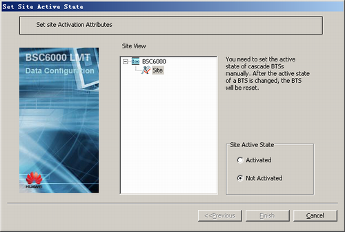
- Activating a BTS.
- On the Management Tree tab page of the BSC6000 Local Maintenance Terminal, right-click the target BTS and choose from the shortcut menu. A dialog box is displayed, as shown in Figure 20.