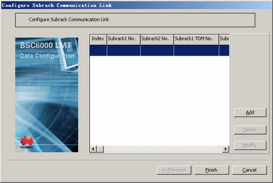
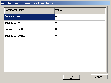
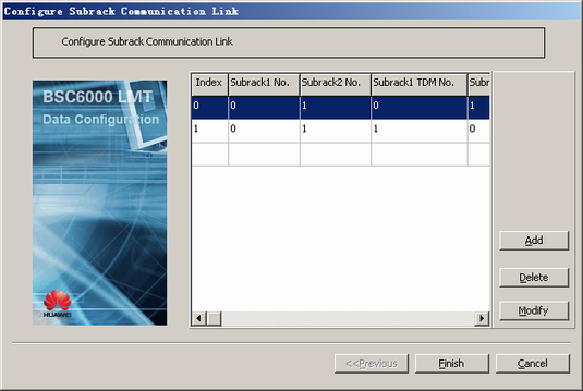
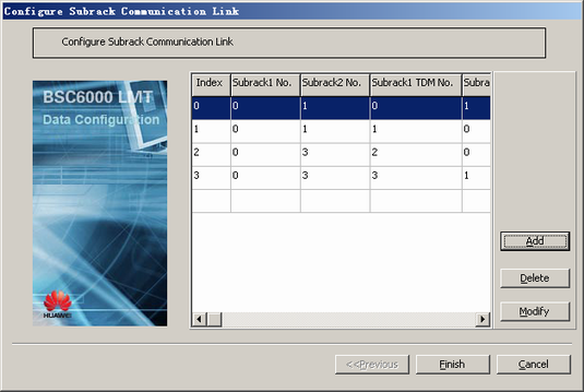
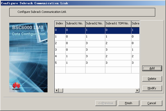
This describes how to configure the communication links between the GMPS and the GEPS, between GEPSs, or between GTCSs. The links are responsible for the TDM switching between subracks.
| Scenario | BSC initial configuration and BSC capacity expansion |
| Mandatory/Optional | Optional. Perform this operation when the default attributes of the communication links between subracks need to be modified. |
- By default, the communication links between fully connected subracks are configured by the LMT software when subracks are added. The attributes of the communication links between subracks can be modified.
- A maximum of three communication links can be configured between two subracks. In actual situations, a pair of active and standby communication links are usually configured between subracks.
- The communication between subracks is achieved through the GTNU in each subrack. There are six external ports, numbered TDM0-TDM5, on the panel of the GTNU. Each port can be used by only one communication link between subracks.
Prerequisite
Preparation
Assume that the BSC is configured with one GMPS, two GEPSs, and two GTCSs. The GMPS is subrack 0, GEPSs are subracks 1 and 3, and GTCSs are subracks 6 and 7.
The following procedure takes how to configure the mesh interconnection between subracks in TDM transmission mode as an example.
Parameter |
Example |
Source |
|---|---|---|
Subrack1 No. |
0 |
BSC internal planning |
Subrack2 No. |
1 |
BSC internal planning |
Subrack1 TDM No. |
0 (active), 1 (standby) |
BSC internal planning |
Subrack2 TDM No. |
0 (active), 1 (standby) |
BSC internal planning |
Parameter |
Example |
Source |
|---|---|---|
Subrack1 No. |
0 |
BSC internal planning |
Subrack2 No. |
3 |
BSC internal planning |
Subrack1 TDM No. |
2 (active), 3 (standby) |
BSC internal planning |
Subrack2 TDM No. |
0 (active), 1 (standby) |
BSC internal planning |
Parameter |
Example |
Source |
|---|---|---|
Subrack1 No. |
1 |
BSC internal planning |
Subrack2 No. |
3 |
BSC internal planning |
Subrack1 TDM No. |
2 (active), 3 (standby) |
BSC internal planning |
Subrack2 TDM No. |
2 (active), 3 (standby) |
BSC internal planning |
Parameter |
Example |
Source |
|---|---|---|
Subrack1 No. |
6 |
BSC internal planning |
Subrack2 No. |
7 |
BSC internal planning |
Subrack1 TDM No. |
0 (active), 1 (standby) |
BSC internal planning |
Subrack2 TDM No. |
0 (active), 1 (standby) |
BSC internal planning |
Procedure
- Configure the communication link between GMPS 0 and GEPS 1.
- Configure the communication link between GMPS 0 and GEPS 3.
- Configure the communication link between GEPS 1 and GEPS 3.
- Configure the communication link between GTCS 6 and GTCS 7.
