
This section provides illustrations and instructions for connecting to the SDI and external sync connectors on the NVIDIA Quadro FX 4500/5500 SDI cards.
For instructions on other NVIDIA Quadro FX SDI cards, see SDI Connections - Other NVIDIA Quadro FX SDI Cards.
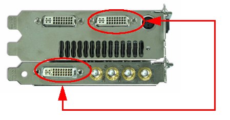
Connect one end of the DVI cable to the DVI connector on the SDI Output card and the other end to the "north" DVI connector on the NVIDIA Quadro FX 4500/5500 card as shown. The SDI output will not work if the cable is not connected to these two connectors.

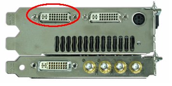
Connect your display to the DVI connector indicated:

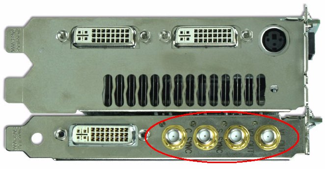
The connector locations for the house sync input and SDI output are shown in the figure below, with corresponding descriptions in the following table. The order of the connector descriptions in the table follow the same left-to-right order of the connectors in the figure.

|
C SYNC |
S SYNC |
V2 Out |
V1 Out |
|
Composite genlock sync signal |
SDI genlock sync signal |
Single link SDI output, or Key portion of a dual link SDI output
|
Single link SDI output, or Fill portion of a dual link SDI output |
The NVIDIA Quadro FX 4500/5500 SDI uses SMA connectors for the house sync input and SDI output connections. Use the provided SMA-to-BNC cables to make the connections as follows:
(Optional) Install the identification colour bands.
Use the provided colour bands to assist in properly identifying the function associated with each SMA-to-BNC cable.
Using a different colour for each SMA-to-BNC cable, place the band over the SMA connector end (the smaller end) and push up to the BNC-connector end.
Position the band snugly over the wide portion of the insulation next to the BNC connector.
Connect the SMA-to-BNC Cables.
Screw the male SMA cable end onto the female SMA connector on the SDI output card.
![]() Note:
Use care when connecting, disconnecting, or handling the cables that you
do not break the centre conductor on the SMA cable end.
Note:
Use care when connecting, disconnecting, or handling the cables that you
do not break the centre conductor on the SMA cable end.
If you installed the colour bands, record which colour corresponds to which connector for later reference.