Autodesk 3ds Max Tutorials > Modeling Tutorials > Modeling a Low-Poly Character > Modeling a Low-Poly Head >
Setting Up the Scene
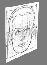
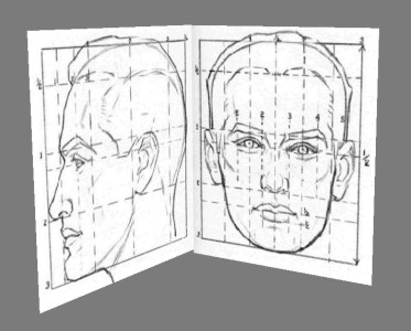
Whether you are modeling an alien, cartoon, or realistic head, you must pay attention to the proportions of your reference material, as well as any details that highlight key features in your character's face.
For this tutorial, you will use two references images that will guide you through this process, and also help you better understand he proportions that come into play when modeling a full head.
Before you begin, note the resolution (in pixels) of the reference image you've created. If you are using the files that have been provided for this tutorial, their resolutions are as follows:
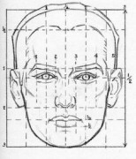
Front reference image: 234 (width) x 274 (height).
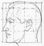
Side reference image: 264 (w) x 274 (h).
Create the front reference plane:
 Go to
the Modify panel. On the Parameters rollout, set Length to 274 and
Width to 234.
Go to
the Modify panel. On the Parameters rollout, set Length to 274 and
Width to 234.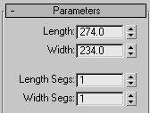
 On the
main toolbar, click Select And Move.
On the
main toolbar, click Select And Move.This places the plane’s pivot point at the world origin.
Map a reference image:
This lets you see the map without any help from scene lights.
This opens the Select Bitmap Image File dialog.
 Click
the Show Map In Viewport button to toggle it on.
Click
the Show Map In Viewport button to toggle it on. With
the plane object still selected, click the Assign Material To Selection
icon to apply the newly created material to the plane.
With
the plane object still selected, click the Assign Material To Selection
icon to apply the newly created material to the plane. You can now see the material on the plane in the Perspective viewport.
Create the side reference plane:
Now that you have created the front-view plane, you'll repeat the procedure to create an additional plane based on the side view.
 On the Main toolbar, click Angle Snap Toggle.
This lets you rotate your objects with precision using static increments.
 Click Select And Rotate,
then hold Shift and in
the Perspective viewport rotate the plane 90 degrees about the Z
axis (the horizontal ring of the rotate gizmo). The Clone Options
dialog appears on release. Click OK. Go to
the Modify panel. On the Parameters rollout, change the Width to 264.
Click Select And Rotate,
then hold Shift and in
the Perspective viewport rotate the plane 90 degrees about the Z
axis (the horizontal ring of the rotate gizmo). The Clone Options
dialog appears on release. Click OK. Go to
the Modify panel. On the Parameters rollout, change the Width to 264.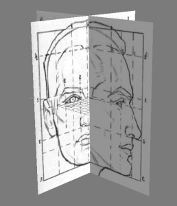
Adjust the virtual studio:
Before you can start modeling the character, you need to adjust the positions of the reference planes.
Currently, only the Perspective viewport is shaded.
Select
the side reference plane and move it on the X axis (red axis) to
the left edge of the virtual studio.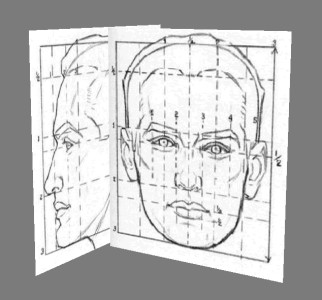
This swaps viewports for a better profile view of the face.
Freeze the reference planes:
Now that the reference planes are in place, you'll freeze them to prevent accidentally moving them.
 Select
the two reference planes and go to the Display panel.
Select
the two reference planes and go to the Display panel.