Autodesk 3ds Max Tutorials > Modeling Tutorials > Modeling a Low-Poly Character > Modeling a Low-Poly Head >
Creating the Basic Head Divisions
In this lesson, you start shaping the rough volume of the head from a simple box primitive. The goal is to shape your initial object as much as you can to match the basic proportions of the references planes; this will help later on when you add details to the mass.
Align a box primitive with the reference planes:
 Click
the Move tool. Then, on the status bar, set the position values
in X, Y, and Z to 0.0.
Click
the Move tool. Then, on the status bar, set the position values
in X, Y, and Z to 0.0. This aligns the box's pivot point at the world origin.
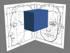
The box's pivot point is centered on all three axes.
You can now follow the reference images as guides while modeling.

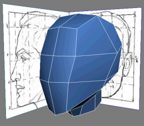
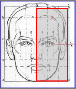
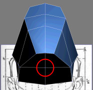
Adjust your box so it covers most of the head and neck.
You could also choose to convert your model to an editable mesh and get still similar results. An editable mesh uses only triangular polygons while an editable poly can be composed of polygons of more than three sides. This means that a square polygon (composed of two triangle faces) contains an invisible edge, also known as a diagonal, as an editable poly, but not as an editable mesh.
Both methods have their distinctions in their respective modeling tools and settings. They are meant to be complementary to one another. However, in this tutorial, editable polys are preferred because we mainly deal with quad polygons, which are better suited for good edge flow.
Add a symmetry modifier:
 On the
Modify panel click the Polygon button.
On the
Modify panel click the Polygon button.You are now at the Polygon sub-object level.
Shape the head and extrude the neck:
 Highlight
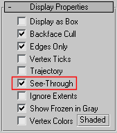
Editable Poly in the Modifier stack. Click Show End result On/Off
Toggle to display both sides of Low-Poly Head while
you're modeling.
Highlight
Editable Poly in the Modifier stack. Click Show End result On/Off
Toggle to display both sides of Low-Poly Head while
you're modeling. Go into
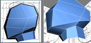
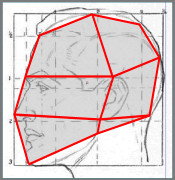
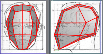
Vertex sub-object level. Adjust your mesh vertices in the Right
viewport to match the reference image.
Go into
Vertex sub-object level. Adjust your mesh vertices in the Right
viewport to match the reference image.The positioning of the vertices following the reference image is mainly based on the face's key features, such as the top of the ear and where the forehead meets the hairline. Even though these are only the first steps in this modeling exercise, providing good anchor points to start from can guide you later on when things get more complex.
 To make
sure to select all overlapping vertices, click Rectangle Selection Region and
drag a region around the desired vertices; this will select every
vertex within this defined region.
To make
sure to select all overlapping vertices, click Rectangle Selection Region and
drag a region around the desired vertices; this will select every
vertex within this defined region.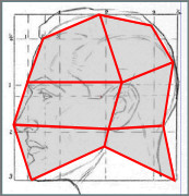
While pressing Delete deletes the sub-object selection as well as any immediate sub-objects (such as edges and polygons), Remove eliminates only the sub-object selection and then combines the polygons that use them.
 While
the resulting vertices are selected, hold Shift and
click the edge button on the Selection rollout to convert your sub-object
selection to border edges.
While
the resulting vertices are selected, hold Shift and
click the edge button on the Selection rollout to convert your sub-object
selection to border edges.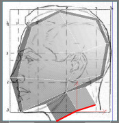
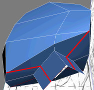
The neck now has the same amount of faces as the head. Click Cut once more or right-click in the active viewport to exit the Cut tool.
Go back
to the Vertex sub-object level and adjust the vertices to round
out the neck.