


Using the Editable Poly Tools
3ds Max has a set of handy editable poly tools that improve the way you can clean up and add detail to your models.
This set of lessons focuses on several tools.
Set up the lesson:
Detail the air intakes:
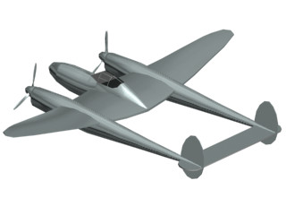
The first detail you'll add are the air intakes on the sponsons of your Lightning. The sponson is the long extension between the wings and the tail section of the airplane.
 In the
Right viewport, Zoom Region around the sponson between the wing
and tail.
In the
Right viewport, Zoom Region around the sponson between the wing
and tail.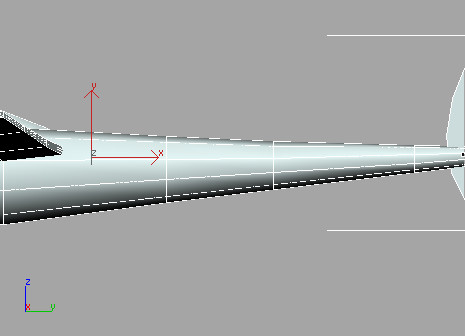
 Go to
the Modify panel and click the Editable Poly entry in the modifier
stack.
Go to
the Modify panel and click the Editable Poly entry in the modifier
stack. Click
the Show End Result On/Off Toggle button that is located along the
bottom of the modifier stack.
Click
the Show End Result On/Off Toggle button that is located along the
bottom of the modifier stack.Turning on this toggle lets you see the results of additional modifiers all way up the modifier stack. You now see the other half of the airplane generated by the Symmetry modifier that was used in the sample file you opened for this lesson.
 On the
Selection rollout, click the Polygon button and make sure Ignore
Backfacing is off.
On the
Selection rollout, click the Polygon button and make sure Ignore
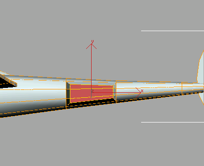
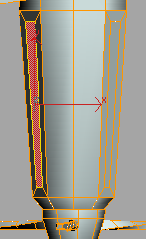
Backfacing is off. Activate
the Select Object tool and drag a window across the three polygons
in the center of the sponson. Make sure the polygons at the top
and bottom are not selected.
Activate
the Select Object tool and drag a window across the three polygons
in the center of the sponson. Make sure the polygons at the top
and bottom are not selected.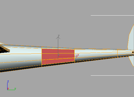
Because Ignore Backfacing is off, you've also selected the same three polygons on the other side of the sponson, for a total of six.
 On the
Edit Polygons rollout, click the Settings button next to the Bevel
tool.
On the
Edit Polygons rollout, click the Settings button next to the Bevel
tool.The Bevel Polygon dialog appears.
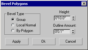
The air intake starts to take form.
Using the Symmetry modifier ensures that changes you make to the original half of the airplane are automatically reflected in the mirrored half.
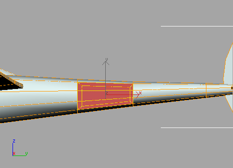
Make
sure Select Object is still active, and then click the Grow button
on the Selection rollout.Grow increases the polygon selection to include polygons that share a common edge.
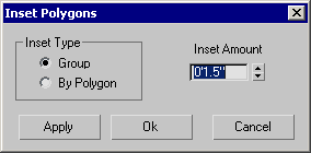
Click
the Settings button next to the Inset tool in the Edit Polygons
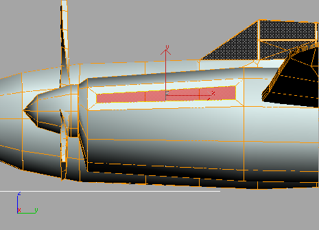
rollout.The Inset Polygon dialog appears.
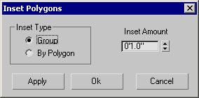
Inset creates new polygons from the current selection by offsetting their edges toward the inside.
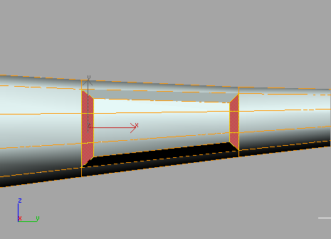
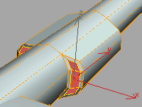
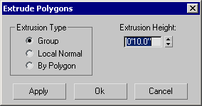
Click
the Settings button next to the Extrude tool in the Edit Polygons
rollout.The Extrude Polygon dialog appears.
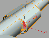
The air intakes are now complete. Next, you'll build some engine exhaust ports.
Add engine exhaust ports:
Next, you'll add exhaust ports to either side of the forward section of the sponson near the propellers. Continue with the model you saved during the previous exercise, or open low_poly_p38_03.max. If you load this file, select the airplane, go to the Modify panel, and access the Polygon sub-object level of Editable Poly.
In the
Top viewport, use Region Zoom to zoom into the right-side engine/propeller
section.
Make
sure the Show End Result On/Off Toggle button at the bottom of the
modifier stack is on. Turn
on Select Object and select the polygons at the left and right sides
of the engine housing. If selected polygons do not appear in red,
press the F2 key on the
keyboard.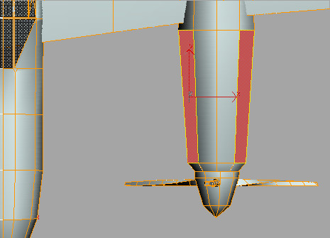
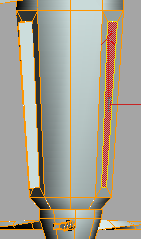
Activate
the Right viewport and use Region Zoom to center the view around
the engine section. If necessary, deselect polygons until only the
topmost polygons on the engine housing are selected. Press F2 to display selected polygons in
red.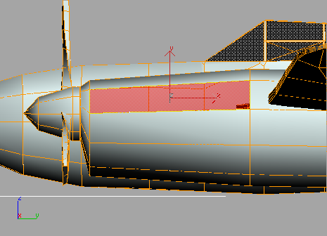
Click
the Settings button next to the Inset tool in the Edit Polygons
rollout.The Inset Polygon dialog appears.
Click
the Settings button next to the Hinge From Edge tool in the Edit
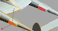
Polygons rollout.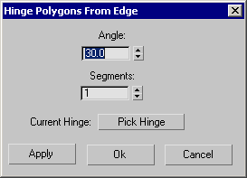
The button text changes to Edge 1051. This will cause a hinged face to be created at this edge.
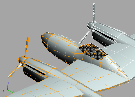
View of the engine exhaust ports you've added