The P-38 was a rugged aircraft because it had twin sponsons that supported the tail, housed the engines and superchargers and contained self-sealing fuel tanks. The airplane could sustain damage to either side, and still fly, thus presenting a formidable challenge to any opponent in a dogfight.
In this lesson, you'll model the sponsons using the same techniques you've already practiced on the wing and tail section. You'll also use the Bevel tools to create the engine exhaust gates.
Create the starboard sponson:
 On the
Create panel, click Cylinder.
On the
Create panel, click Cylinder.The Cylinder button turns gold, showing it is active and ready to use.
Don't worry about the height, you'll adjust that in a moment. Drag the height to any value.
 In the
Top viewport, move the cylinder so it is over the sponson on left
side of the background image (this is actually the right side of
the plane, hence “starboard”). Position it so the rounded cap at
the end, called the propeller spinner, is visible.
In the
Top viewport, move the cylinder so it is over the sponson on left
side of the background image (this is actually the right side of
the plane, hence “starboard”). Position it so the rounded cap at
the end, called the propeller spinner, is visible.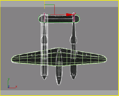
 Go to
the Modify panel. From the Modifier List, find the Object-Space
Modifiers group, and choose Taper.
Go to
the Modify panel. From the Modifier List, find the Object-Space
Modifiers group, and choose Taper.
Tapered sponson aligned with the background image.
(The front of the sponson is just behind the propeller spinner.)
 In the
Front viewport, rotate the sponson about 15 degrees about its Y
axis so the left and right sides are vertical.
In the
Front viewport, rotate the sponson about 15 degrees about its Y
axis so the left and right sides are vertical.Later in this lesson, you'll further shape the sponson by repeating the same technique as before: converting to Editable Poly, selecting rows of vertices, and moving them into position over the background image.
But first you'll create the propeller cap, or “spinner,” at the forward end of the cylinder using a hemisphere and AutoGrid.
Add the propeller spinner:
 Zoom
into the Perspective viewport so you have a close view of the front
end of the cylinder. Right-click the viewport label, and set the
shading mode to Smooth + Highlights and Edged Faces.
Zoom
into the Perspective viewport so you have a close view of the front
end of the cylinder. Right-click the viewport label, and set the
shading mode to Smooth + Highlights and Edged Faces.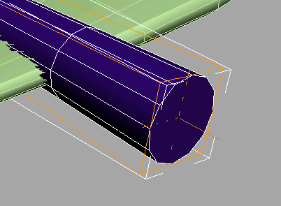
Open
the Create panel. In the Object Type rollout, click to turn on Sphere.An axis tripod follows your cursor, showing you where the sphere will be drawn.
This lets you draw a sphere off the end of the cylinder.
It doesn't matter what size; you will adjust the parameters after you draw it.
Now instead of a sphere, there is a hemisphere.
Rotate
the hemisphere so the 12 segments of the cylinder and the hemisphere
are at the same angle. Fifteen degrees about the Y axis. On the
toolbar, click the Align button, then click the cylinder. In the
Align Position (World) group, turn on X Position and Z Position.
This properly aligns the hemisphere and the cylinder. Click OK
On the
toolbar, click the Align button, then click the cylinder. In the
Align Position (World) group, turn on X Position and Z Position.
This properly aligns the hemisphere and the cylinder. Click OK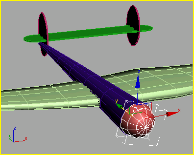
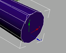
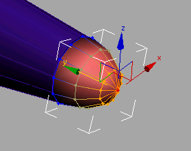
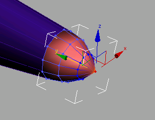
The spinner is aligned to the end of the sponson.
You'll be converting the sponson cylinder to an editable poly so it's a good time to save your scene.
Finish shaping the sponson:
 In the
Selection rollout, click Vertex.
In the
Selection rollout, click Vertex. In the
Left viewport, select a column of vertices and then on the toolbar,
choose Non-Uniform Scale from the scale flyout. Non-uniform scale
them closer together, watching the bitmap as a guide. Then right-click,
choose Move from the quad menu, and position the row.
In the
Left viewport, select a column of vertices and then on the toolbar,
choose Non-Uniform Scale from the scale flyout. Non-uniform scale
them closer together, watching the bitmap as a guide. Then right-click,
choose Move from the quad menu, and position the row.
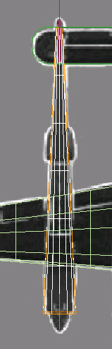
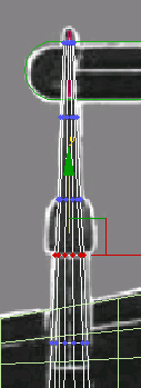
Select one column at a time, scale, then move.
 Click
the Vertex selection button to turn it off, then select the spinner
hemisphere in the viewport. Select
the cylinder again and turn on Vertex selection.
Click
the Vertex selection button to turn it off, then select the spinner
hemisphere in the viewport. Select
the cylinder again and turn on Vertex selection.This returns the end of the cylinder to a more circular shape.
Finish the propeller spinner:
Click
the Vertex selection button to turn it off.The sponson is almost finished. There is a blister on either side of the sponson that serves as the exhaust waste gate outlet. You'll create this next, using the Bevel features.
Create the exhaust gate outlet:
Turn
on Vertex selection for the sponson.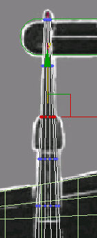
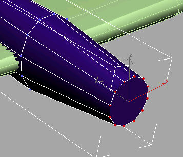
Select and move these red vertices down.
Select and move these red vertices up.
The vertices now line up in the top view, but need adjustment in the left view.
 On the
Selection rollout, choose Polygon.
On the
Selection rollout, choose Polygon.This lets you select polygons instead of vertices.
 Make
sure the Select Object button is turned on. In the Left viewport,
drag a selection window over the polygons shown in the illustration
below.
Make
sure the Select Object button is turned on. In the Left viewport,
drag a selection window over the polygons shown in the illustration
below.The selected polygon displays in red. If you don't see a fully shaded polygon, only surrounding edges, right-click the Left viewport label and choose Configure. In the Rendering Options group, turn on Shade Selected Faces.
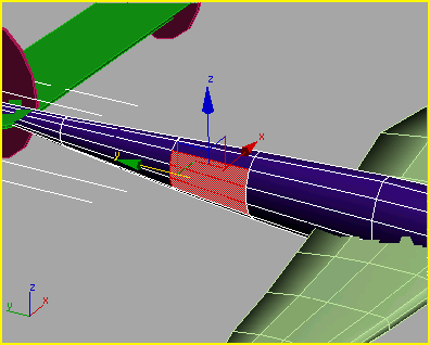
Dragging the selection window over these three polygons in the Left viewport also selects the three polygons on the opposite side of the sponson.
 On the
Edit Polygons rollout, click the Bevel Settings button to open the
Bevel Polygons dialog.
On the
Edit Polygons rollout, click the Bevel Settings button to open the
Bevel Polygons dialog.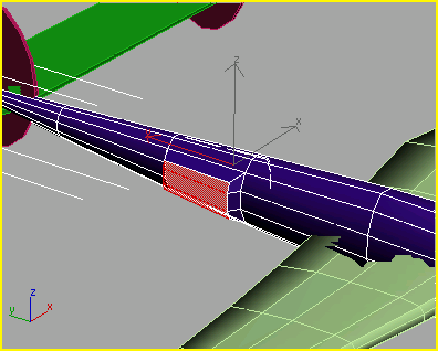
 Region
Zoom around the exhaust gate in the Left viewport.
Region
Zoom around the exhaust gate in the Left viewport.Because you have Lock Zoom/Pan turned on for the background image, you might see a dialog warning that some amount of memory is necessary to redisplay the background. Click Yes.
This will also select the polygons on the opposite side of the sponson.

Click the Bevel Settings
button and set the Height to -0.1m and the
Outline Amount to -0.025m
. Click OK.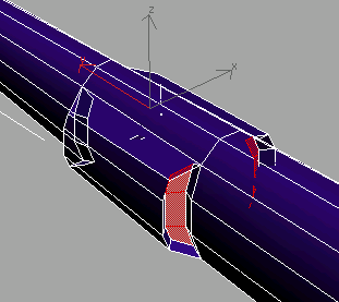
Next, you’ll clone the starboard sponson and spinner to make the port sponson and spinner.
Clone the sponson:
Now both objects are selected.
In the
Top viewport, hold down the Shift key
and move the selected objects to the right.The Clone Options dialog appears.
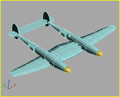
The P-38's wing, sponsons, and tail
All that remains is the central gondola and canopy detail.


