There are many different modeling approaches you could take to building the wings. Here, you'll use a Box primitive with a Taper modifier.
You'll be continuing from the previous section, Setting Up Viewport Backgrounds or open p38_calibrated_start.max from the \tutorials\p38_lightning folder.
Create the wing using a box:
 On the
Create panel, on the Object Type rollout, click Box.
On the
Create panel, on the Object Type rollout, click Box.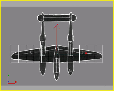
The Box with 12 width and 3 length segments.
You need to increase the number of segments so the modifiers for tapering and bending the wings will work correctly.
The object is now named wing.
Next you'll change the shape of the wing's profile so it looks like an airfoil.
Shape the wing into an airfoil:
 From
the viewport navigation controls, click Zoom Extents.
From
the viewport navigation controls, click Zoom Extents.You'll zoom in on the wing object.
You'll need this to perform some sub-object editing to the vertices that make up the wing.
 In the
Selection rollout, click the Vertex button.
In the
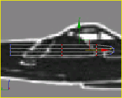
Selection rollout, click the Vertex button.Look at the box in the Left viewport with vertex selection on. Each tick you see is actually twelve vertices lined up on top of one another. When you want to select and move them, you need to drag a selection window around them. Otherwise you will only select one vertex, rather than all of them.

The vertices appear as blue ticks at every intersection of the model.
The X,Y,Z tripod jumps to the selection set and the selected ticks turn red.
Selected vertices display in red.
The Ctrl key allows you to add to an existing selection set. The X,Y,Z tripod jumps to the center of the selection set.

 On the
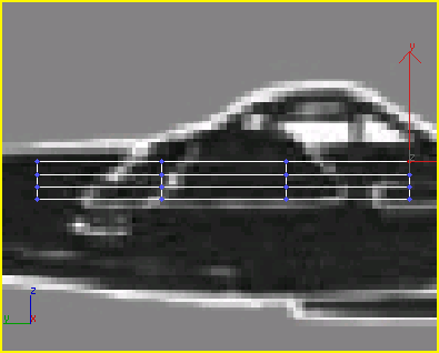
main toolbar, click the Select and Move button and move the cursor
over the X axis of the tripod. Click and drag the cursor to the
left so the leading edge of the wing looks beveled.
On the
main toolbar, click the Select and Move button and move the cursor
over the X axis of the tripod. Click and drag the cursor to the
left so the leading edge of the wing looks beveled.
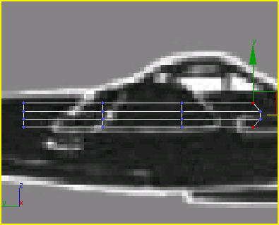
 Click
Select And Non-Uniform Scale. Then scale the vertices along the
Y axis to 75%.
Click
Select And Non-Uniform Scale. Then scale the vertices along the
Y axis to 75%.
Scale the vertices to start rounding off the leading edge of the airfoil.
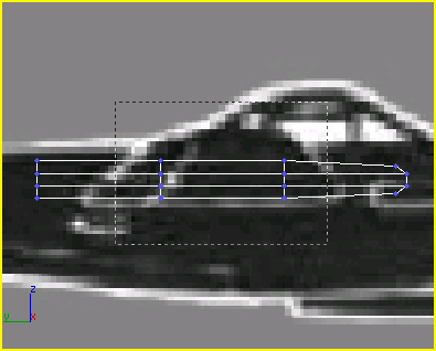
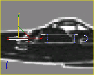
Move
this set of vertices along the X axis to the right about 0.5m.Again, watch the coordinate readout at the bottom.
Move
this set of vertices along the X axis to the right about 0.8m.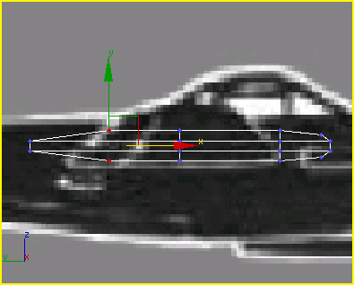
The airfoil is beginning to take shape.
Click Select And Non-Uniform
Scale, hold down the Ctrl key
and drag a selection window around all the left-most set of vertices.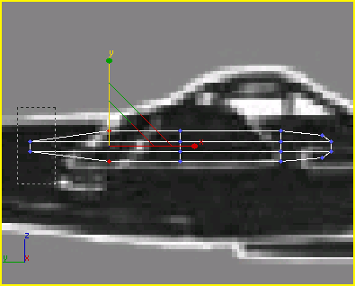
Now you've got a pretty good approximation of an airfoil.
Now that you have your airfoil, you'll make further changes to the shape of the wing using a Taper modifier.
Add a taper modifier:
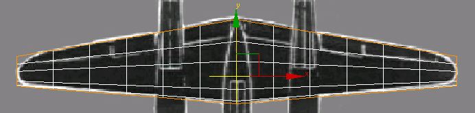
Activate
the Top viewport, and make sure to turn off Vertex mode.An orange taper gizmo appears in the viewport over the box.

The box is starting to resemble the P-38's wing shape.
Next you'll move the Taper Center to refine the wing’s shape.
 In the
modifier stack display, expand the Taper hierarchy by clicking the
box marked with a plus sign. When the Taper expands, click Center.
In the
modifier stack display, expand the Taper hierarchy by clicking the
box marked with a plus sign. When the Taper expands, click Center.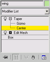
At the Center sub-object level, you can adjust the location of the center of the Taper. Moving a modifier’s center will alter its results.
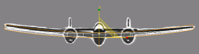
Activate
the Front viewport and move the wing along the Y axis so it is centered
over the background bitmap.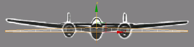
Move the wings up in the Front viewport.
Next you'll convert the box to an editable polygon object, and then move some vertices to round off the wing tips.
Convert the box:
The box is now an editable poly object.
Round off the wing tips:
On the
Selection rollout on the command panel, click Vertex.Some vertices from previous operations are already selected.
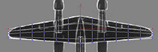
Select the vertices at each end of the wing.
On the main toolbar, click
Select And Non-Uniform Scale. Then use the Transform gizmo to scale
the vertices in the top view so the ends of the wing tips are rounded.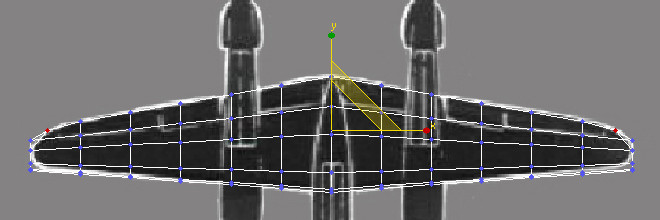
Scale the vertices to round off the wing tips.
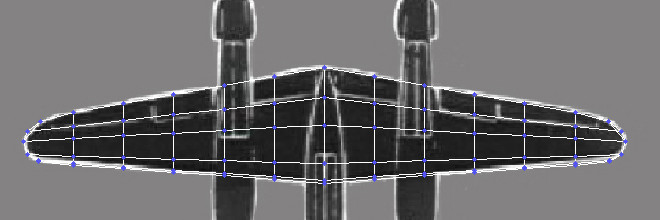
The wing tips are rounded.
In the Top viewport you need to select all the vertices on the outside edges of the wings. You can accomplish this by using the selection rectangle with the Ctrl key.
Add a Bend modifier:
Bend the wings up.
Next, you'll add the stabilizers and rudders. These are easy to do.


