Modeling a Pawn

Modeling a Chess Set

Modeling a Bishop

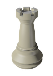
Modeling a Rook
In this lesson, you will model a rook for the
chess set. You'll build the rook the same way as in the previous
lessons, where you created a pawn and a bishop, except for the top
part with the battlement. If you were making a wooden chess set,
you wouldn't be able to use a lathe for this part of the piece,
and so it is with the 3D model: Although the basic structure of
the rook is a lathed spline, like the pawn and the bishop, its top
requires a different modeling technique.
Features and techniques covered in this lesson:
- Using
face extrusion to change geometry.
- Adjusting
smoothing groups for better results.
Time to complete: 15 minutes
Set
up the lesson:
- Open
the rook_outline_edited.max file.
This file contains the basic shape of the rook.
If you prefer to build the rook from scratch, delete the profile
and recreate it as you did in the previous lessons with the pawn
and the bishop. Make sure, however, that you do not take into account
the battlement at the top of the rook, as you will create it later
using polygon extrusions.
The Front viewport should contain a reference
image. If you cannot see the image, perform the following steps:
- Make
sure the Front viewport is active and then press Alt+B to open the Viewport Background
dialog.
- On
the dialog, click the Files button.
- Locate
the ref-chess.jpg image
in the \intro_to_modeling folder and
double-click it.
Lathe
the basic shape:
-
 On the
main toolbar, choose the Select tool. Select the spline representing
the rook’s profile in any viewport.
On the
main toolbar, choose the Select tool. Select the spline representing
the rook’s profile in any viewport. -
 With
the spline selected, go to the Modify panel. From the Modifier list,
choose Lathe.
With
the spline selected, go to the Modify panel. From the Modifier list,
choose Lathe. - On
the Parameters rollout, click the Min button in the Align group.
- Set
Segments to 36 and turn on Weld Core.
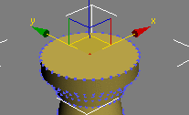
Prepare
the top for the battlement:
- With
the rook still selected, make sure you are still in the Modify panel.
From the Modifier list, choose Edit Poly.
-
 On the
Selection rollout, click the Polygon button.
On the
Selection rollout, click the Polygon button. - Try
selecting the top of the rook.
You can only select a fraction of the area;
1/36th of the top area, to be exact.
-
 On the
Selection rollout, click the Vertex button.
On the
Selection rollout, click the Vertex button. - Select
the vertex in the top-center area of the rook.
- Hold
the Ctrl key down
and click the Polygon button again on the Selection rollout. All
polygons connected to the selected vertex are automatically selected.
- Press F4 to turn on Edged Faces display,
if necessary. This allows you to see the shaded object and its underlying
geometry.
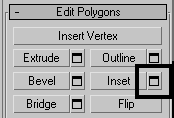
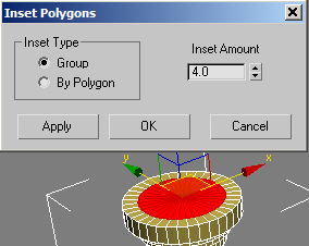
- On
the Edit Polygons rollout, click the Settings button next to Inset.
- In
the dialog that appears, set Inset Amount to 4.0.
- Click
OK to close the dialog and save the inset.
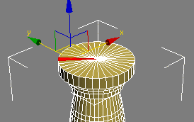
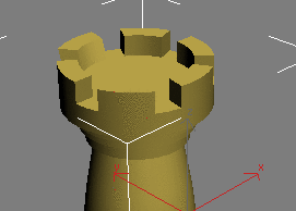
Create
the battlement:
- Open
the Modify panel, if necessary.
-
On the
Selection rollout, make sure you're at the Polygon sub-object level.
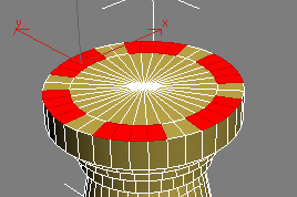
-
Use
the Select tool to select four adjacent polygons in the outer ring.
- Skip
the next two polys and then select the four after those. Repeat
the procedure around the circumference until the selection resembles
the following illustration:
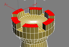
- On
the Edit Polygons rollout, click the Settings button next to Extrude.
On the dialog that appears, set the Extrusion Height value to 4.5 to
match the height of the battlement in the reference image in the
Front viewport (change the value if necessary). When you are finished,
click OK to save the extrusion and exit the dialog.
- On
the Selection rollout, click the Polygon button to exit this level.
- Press F4 to exit Edged Faces display.
Note the faceted effect on the battlement. You
will fix that in a moment.
Adjust
smoothing groups:
- Make
sure the rook object is still selected and that you are still at
the Modify panel.
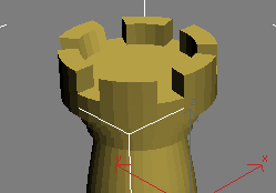
- From
the Modifier list, choose Smooth. The entire rook now appears faceted.
- In
the Parameters rollout, turn Auto Smooth on and leave Threshold
at the default value of 30.0. Any two adjoining faces that meet at
an angle less than that value will be made part of the same smoothing group
and no edge will appear between them.
Summary
In this lesson you learned to create new geometry
using face extrusion. You also learned how to use smoothing groups
to give your objects a smoother look.