


Using File Link with AutoCAD Drawings
As you experienced in the previous lessons, the Import functionality of 3ds Max allows you to load drawings and models that were created with AutoCAD, AutoCAD Architecture, or AutoCAD Mechanical. A drawing or model is imported and you can begin making alterations using the tools in 3ds Max.
Importing is fine for a drawing or model that is no longer being updated, but what about a drawing that is still being developed? Architectural drawings can change greatly in a matter of hours, so if you're building a 3D model based on an imported drawing that is still in flux, you will find yourself changing and rebuilding many objects before the project is finished. Perhaps, completely starting over if the drawings change a lot.
This is a situation where using the File Link Manager is invaluable. This lesson will show you the advantages of the tool and how it will save modeling time.
Set up the lesson:
This is to preserve the original drawing so the tutorial can be easily repeated.
Make the link:
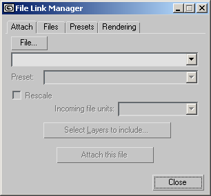
The File Link Manager dialog is displayed.
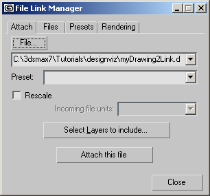
The drawing appears in the file list.
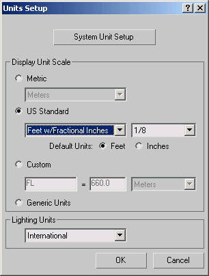
You want the units to match the default unit size in the AutoCAD drawing.
You'll see the Status Bar is replaced with the Linking AutoCAD Drawing progress bar.
Larger, more complex drawing files take longer to link.
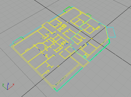
The drawing is linked to 3ds Max.

This panel shows you have one drawing file linked to the scene and the status of the linked file. It also gives you the opportunity to reload, detach or bind a linked file. You'll experiment with these options later.


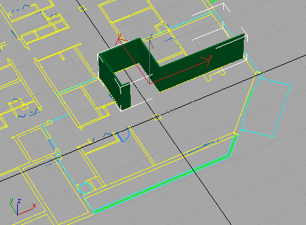
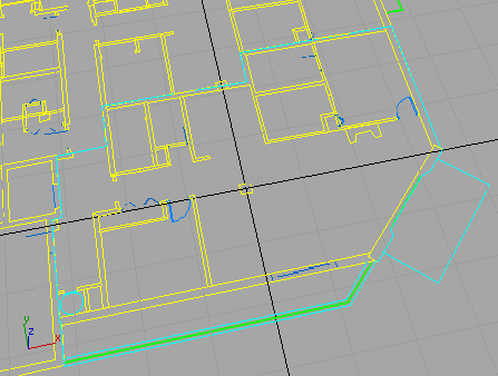
 Use
Pan, Zoom and Arc Rotate to display the apartment you worked on
earlier.
Use
Pan, Zoom and Arc Rotate to display the apartment you worked on
earlier.
What you've just done is create an active link from 3ds Max to a drawing file and verified that the file is linked. Next, you'll start building the model and see how changes to the drawing affect the scene.
Start building a model:
Next you'll build walls, add doors, and assign materials to objects you've created. In this section, you'll start modeling by adding a wall.
 Click the Snaps Toggle button
to activate it, then right-click the same button.
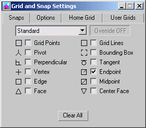
Click the Snaps Toggle button
to activate it, then right-click the same button.Right-clicking the button opens the Grid And Snap Settings dialog.
The Units Setup dialog is displayed.
The drawing, myDrawing2Link.dwg should still be open from earlier when you set up the lesson.
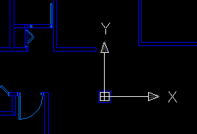
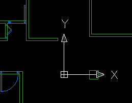
The kitchen wall is extended to facilitate extra cabinet and counter space.
 Save
the drawing and then minimize the AutoCAD window.
Save
the drawing and then minimize the AutoCAD window.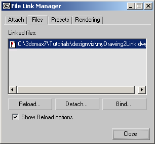
The red flag in the document symbol next to the linked file indicates a change has occurred in the master drawing.
You'll see the Linking AutoCAD Drawing progress bar, again.
The wall in the drawing is extended but the wall you built is not.
This situation is easy to fix by editing the Wall object at a sub-object level and moving the vertex to match the new endpoint. If you want to add a door, its insertion into the wall will be treated just as you learned in the Editing and Creating Objects tutorial .
Next, after resetting the lesson, you'll learn how to manage layers when a drawing is linked.
Reset the lesson:
Manage layers:
In this section, you'll work on a scene that already has a drawing linked, but you're going to use some of the layer-management features of the File Link Manager.
If you see the Units Mismatch dialog, choose to Adopt The File's Unit Scale.
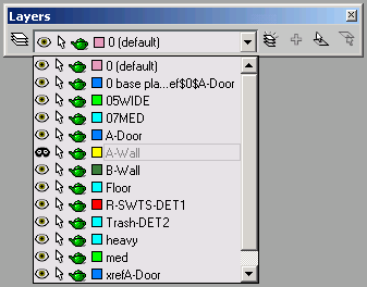
This scene already has a drawing file linked to it, but one of the layers you need was frozen in AutoCAD and by default, frozen layers do not link unless you specify them.
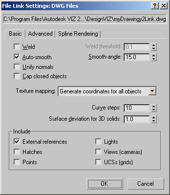
The File Link Settings dialog appears.
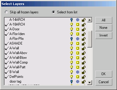
This opens the Select Layers dialog.
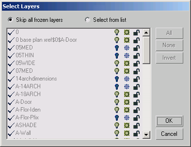
The frozen layers show a snowflake symbol in the middle column. A check mark next to a layer means it will be included when you link a DWG file.
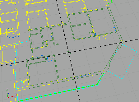
The drawing is reloaded and includes the Layer:B-Wall object.
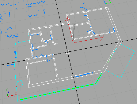
Now that the new layer has been included, you'll use some of the linked geometry to build your model.
Model with linked geometry:
 Open
the Modify panel and choose Edit Mesh modifier from the Modifier
List.
Open
the Modify panel and choose Edit Mesh modifier from the Modifier
List.Doing this assigns an Edit Mesh modifier to the linked geometry.
 From
the Selection rollout, turn on the Polygon sub-object level.
From
the Selection rollout, turn on the Polygon sub-object level.Selected faces are displayed in red.

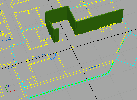
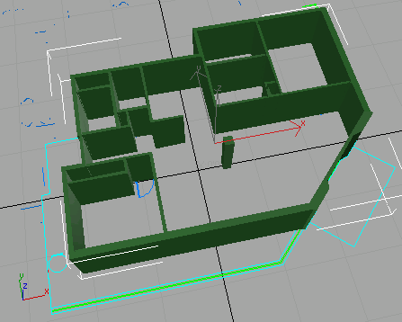
All the walls and the column are extruded.
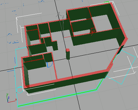
The kitchen wall is extended and the column is lined up with the bedroom wall.
The drawing changes are reflected in the model.
This last set of steps demonstrated how you can use linked geometry as a basis for building a model. Since linked geometry is the basis for this set of walls, they will change as the drawing changes; however, they are only simple extrusions. If, for instance, you wanted to add a door, these walls will not automatically create an opening when the door is placed. You will have to perform a Boolean operation to manually create the opening in the wall where the door is placed.
In this tutorial, you learned about the File Link Manager and how a linked file will update in an 3ds Max scene.