Preparing AutoCAD Drawings for Import

Working with AutoCAD Files

Importing 3D AutoCAD Models

Editing and Creating Objects
In AutoCAD, when line segments meet at a corner,
they are usually joined with crisp, sharp angles. This may translate
to an unappealing or unrealistic appearance in 3ds Max, as most real-world
objects have some amount of curve or fillet on their edges.
In this lesson, you will prepare the drawing
for import by breaking some of the extreme angles with fillets,
creating a floor/ceiling shape and using 3ds Max AEC objects
to build a 3D model.
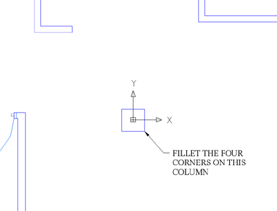
Fillet the Column:
- In
AutoCAD, zoom in to the central column near the origin.
- From
the Modify menu, choose Fillet.
- Press
the R key and then
press Enter so you
can specify a fillet radius. Set the radius to 0.125 and
press Enter.
- Press
the P key and then
press Enter so you
can select a polyline, and then click the square shape of the central
column.
TipThis
is the advantage to using polylines to create your drawings as opposed
to individual lines and arcs. Since the central column shape is
a 2D polyline, you can fillet all the corners at once. Otherwise,
you'd have to repeat the fillet command three more times to break
all the corners.
Create the Floor Perimeter:
At this point, the drawing doesn't contain an
object that you can extrude to create the floor or ceiling. Next,
you'll create a polyline that you'll later import into 3ds Max.
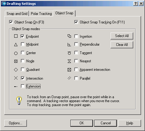
- From
the menu bar, choose Tools > Drafting Settings.
The Drafting Settings dialog is displayed.
- On
the Object Snap panel of the Drafting Settings dialog, make sure
only Endpoint and Intersection are active, and then click OK.
This will snap the endpoints of your new polyline
to the endpoints or intersections of the existing AutoCAD lines.
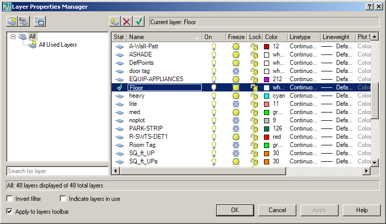
- In
the Layer Properties Manager, create a new layer named Floor and
make that layer current.
- Click
the color swatch for the Floor layer to open the Select Color dialog
and change the layer color to cyan.
TipEach
object imported into 3ds Max retains its assigned layer's color
rather than any color assigned to it. To avoid confusion, steer
clear of using AutoCAD layer colors that are white, red or blue,
as these colors are used by 3ds Max to designate selected objects
(white), selected sub-objects (red), or sub-objects (blue), respectively.
- Click
OK to close the Select Color dialog and then click OK to close the
Layer Properties Manager dialog.
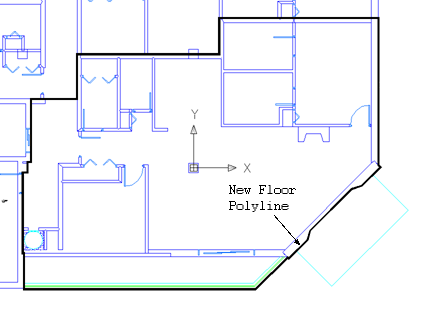
- Use
the Polyline command to draw a polyline around the perimeter of
the tenant space.
Include the balcony and hallway as shown below.
- Save
the file as my2Ddrawing2.dwg.
Import the Drawing:
Now that you have a polyline representing the
floor or ceiling of the apartment, you can import it into 3ds Max and
start building the 3D model. You can continue from the previous
lesson and use your drawing or you can use the sample file that
ships with 3ds Max.
- Open
or reset 3ds Max.
- Choose
File menu > Import. In the Select File To Import dialog, set
the Files Of Type field to AutoCAD Drawing (*.DWG,*.DXF).
- Open my2Ddrawing2.dwg from
the previous section or ww_cad_drawings2_clean.dwg from
the \tutorials\designviz folder.
If the Proxy Objects Detected dialog opens,
click Yes to continue.
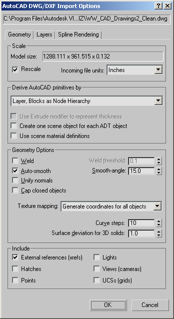
- On
the Geometry panel of the AutoCAD DWG/DXF Import Options dialog,
turn on Rescale and set Incoming File Units=Inches to match the
default unit size in the AutoCAD drawing.
NoteThis
panel also controls what types of objects (hatches, points) are
imported, and whether AutoCAD lights, views, and UCSs are converted
to 3ds Max lights, cameras, or grids.
- Switch
to the Layers tab. By default, the Skip All Frozen Layers option
is active, which allows the drawing to be imported just as it was
last seen in AutoCAD. If a different layering scheme should be employed,
the Select From List option allows you to select the layers to be
imported manually.
- Click
OK.
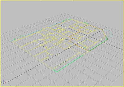
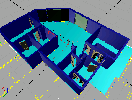
The file is imported into 3ds Max.
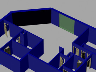
Create AEC Walls:
Now that the floor plan is imported into 3ds Max,
you can use it as a template to create a 3D model. You'll start
this process by adding Wall objects. However, before adding walls
you should review the scene and note the different types of walls
you will have to build.
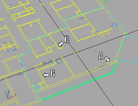
You can see that there are at least three different
types of walls used in the structure. You have heavy, exterior walls
(A), medium weight walls (B), which separate the apartments, and
the thinner, interior walls (C), which separate the rooms in each
apartment.
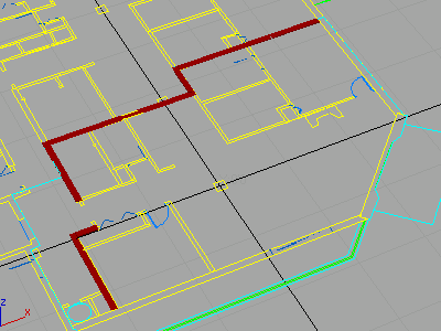
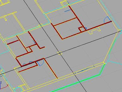
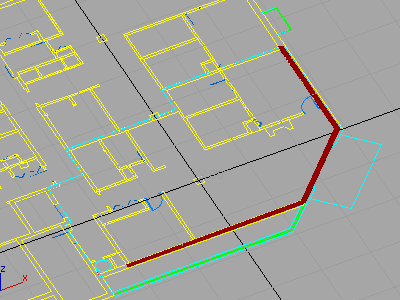
You'll start this section by creating the medium
weight walls that are highlighted in the following image. They run
along the upper part of the drawing and wrap around to the lower
left where they meet the exterior wall.
Build
medium weight walls:
- Continue
from the previous section or open ww_cad_drawing.max from
the \tutorials\designviz folder.
-
 Click the Snaps Toggle button
to activate it, then right-click the same button.
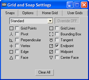
Click the Snaps Toggle button
to activate it, then right-click the same button.Right-clicking the button opens the Grid And
Snap Settings dialog.
- On
the Snaps panel, make sure Endpoint is the only snap setting that
is turned on. Close the dialog by clicking the X button in the upper-right
corner.
TipSetting
the snap options correctly helps considerably in the process of
building walls.
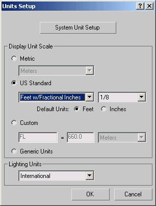
- Open
the Customize menu and choose Units Setup.
The Units Setup dialog is displayed.
- In
the Display Unit Scale group, choose US Standard, set the units
to Feet w/ Fractional Inches, and then click OK.
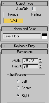
- On
the Create panel, open the Geometry list and choose AEC Extended.
- Click
the Wall button.
- Set
Width to 0'8 3/8”, Height to 9'0”,
and Justification to Right.
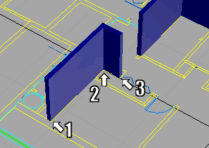
When using a 2D drawing as a template for building
a 3D model, you typically set the justification to Left or Right
so you can trace the floor plan. In this case, the right edge of
the wall’s baseline snaps to the right side of the line you're tracing.
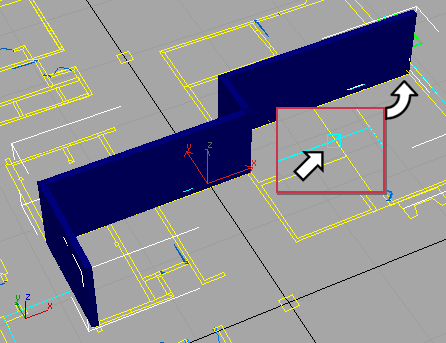
- Click
the upper intersection where the master bedroom wall meets the exterior
wall (inset),
then click again where the wall turns at the outside of the closet.
Continue following the floor plan until you get to the foyer. Right-click
to finish the wall.
TipWhile
building walls, you can use the mouse wheel to zoom in and out and
use the I (letter “i”) key to pan the view.
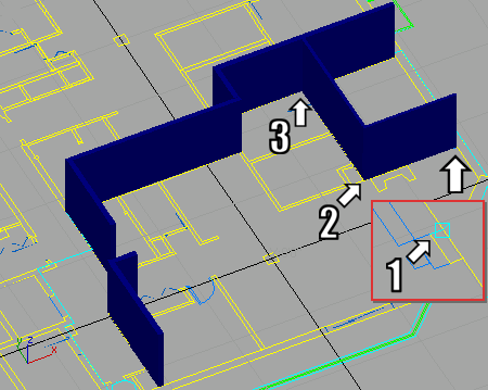
- Click
the inside intersection where the second bedroom wall meets the
exterior wall, then click again at the corner where the wall turns toward
the foyer. Click at the intersection where the closet starts, forming an
“L” shaped wall. Right-click again to end the wall command.
- Save
the scene as my_Walls1.max.
Next, you'll continue to use the Wall command
to build the interior walls.
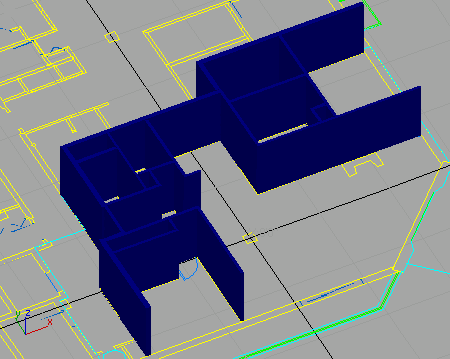
Interior
wall construction:
The interior walls are the thinnest of the three
types of walls you need to create. There are also many more of them,
as highlighted in the following image.
- Click
the Wall button again and set Width to 0'5”.
Leave the Height value at 9'0” and the Justification
setting at Right, for now.
- Click
the intersection where the fireplace wall meets the exterior wall
(see inset), then click again where the wall turns into the master
bedroom. Click again where the wall intersects the rear wall that
separates the apartments. Disregard door openings and build walls
right over them.
- Continue
creating interior walls until you've filled the apartment.
If you notice that the justification of a wall
is incorrect, change the justification setting after the wall is
completed and it will align itself properly.
- After
you've created all the interior walls, save the scene as my_Walls2.max.
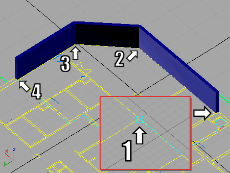
Exterior
wall construction:
There are three exterior walls that you need
to build to finish enclosing the apartment, as shown in the following
image.
- Click
the Wall button again, set Width to 1'2”, and change
justification to Left.
Leave Height at 9'0”.
- Click
the intersection where the second bedroom wall meets the exterior
wall (see inset), then click again where the wall meets the angled patio
door wall. Continue around to finish at the corner where the master bedroom
walls intersects with the exterior wall.
- Right-click
to finish adding walls.
- Save
the scene as my_Walls3.max.
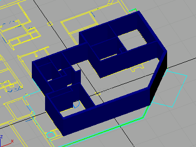
Adjust
the walls:
You might sometimes need to adjust a wall that
you've already constructed, or to combine all the walls you've created
into a single object.
You'll notice that the angled wall where the
patio door is supposed to go is supposed to be thicker than the
other exterior walls. This section of the tutorial demonstrates
how to adjust an existing wall and how to attach all the walls so
they are a single object.
- Continue
using the model from the previous section or open ww_cad_drawing2.max from the \tutorials\designviz folder.
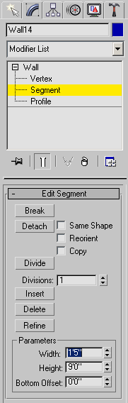
- Select
the wall along the balcony and switch to the Modify panel.
- Open
the Wall object in the modifier stack, highlight the Segment sub-object
level, and then select the angled wall segment where the patio door
should be located.
- In
the Edit Segment rollout, set the Width value to 1'5”.
The selected wall is now 1' 5” thick.
- Go
back to the Wall level in the modifier stack.
You cannot select another wall or object until
you've exited the sub-object level.
- Select
the first wall you created; it separates this apartment from the
one behind it. The wall is named Wall01.
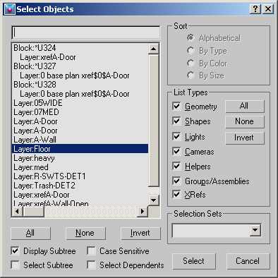
TipYou can also select the wall by pressing
the H key to open
the Select Objects dialog.
- On
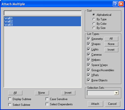
the Edit Object rollout, click Attach Multiple.
The Attach Multiple dialog is displayed.
- Click
the All button at the lower left to highlight all the wall objects
and then click the Attach button.
The walls are combined into a single object.
- Save
your work as my_Walls_Complete.max.
Create AEC Doors:
AEC doors and windows, when properly created,
generate their own openings in AEC walls, thereby eliminating the
need to use Boolean subtraction or otherwise edit the walls to accommodate
them. To do this correctly, the Edge snap must be used.
- Continue
using the model from the previous section or open ww_cad_drawing3.max from the \tutorials\designviz folder.
- Ensure
that the Snaps Toggle button is still active, then right-click the
button to open the Grid and Snap Settings dialog.
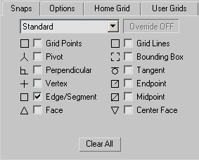
- Turn
on Edge/Segment, turn off all other options, and then close the
dialog.
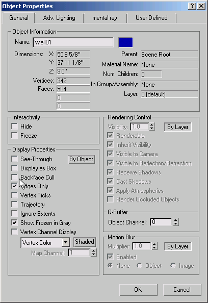
- Select
the wall object, Wall01, right-click, and choose
Properties from the quad menu.
- On
the General panel turn off By Layer in the Display Properties group
and then turn off Backface Cull.
When adding a door, you need to be able to set
two points for the width of the door and a third point to set the
depth, corresponding to the wall thickness. Turning off Backface
Cull lets you see the back edges of the wall for setting the depth.
- Click
OK to close the Object Properties dialog.
- Right-click
the Perspective viewport label and choose Wireframe from the pop-up
menu.
- Zoom
in and pan to the doorway leading into the master bedroom on the
fireplace wall.
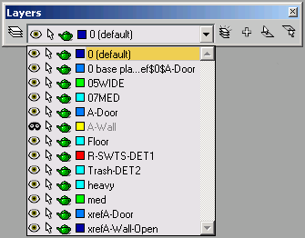
- On
the Layers toolbar, open the Layer list and click the eyeball symbol
to hide layer A-Wall.
In order for a door or window to open a wall
properly, you must select the edges of the wall, not the lines of
the floor plan. Temporarily hiding the A-Wall layer ensures that
you select only AEC Wall edges when placing doors or windows.
- On
the Create panel, open the Geometry list and choose Doors. On the
Object Type rollout, click the Pivot button.
- Place
the cursor at the base of the interior wall near the external wall,
where the door opening begins.
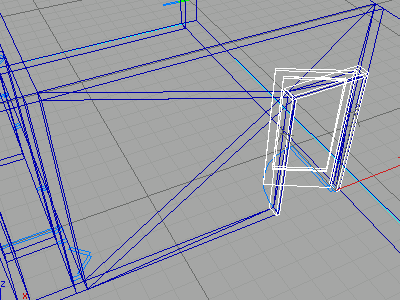
- With
the Edge snap indicated, click and drag the cursor to the opposite
side of the door opening (nearer to the fireplace), then release
to set the width of the door.
- Move
the cursor over the inside-bottom edge of the wall until the edge
snap indicator is visible. Click to set the depth of the door.
- Drag
the mouse upward, then click to set the height of the door.
You can tell a door or window is inserted into
a wall correctly because there are additional edges in the wall
object.
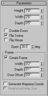
- On
the Parameters rollout, set Height to 7'0”, Width
to 2'6”, and Depth to 5”.
Set the Open value to 30.0 degrees and turn on Flip
Swing so the door swing matches the direction shown on the imported
drawing.
- Click
the object color swatch next to the name of the door to open the
Object Color dialog. Select a new color for the door so it isn't
the same blue as the walls.
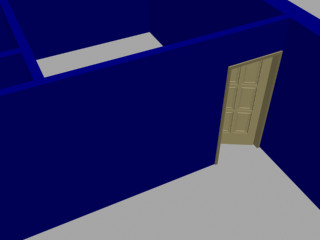
-
 Right-click to end the Pivot door
command and then click the Quick Render button to render the scene.
Right-click to end the Pivot door
command and then click the Quick Render button to render the scene.If you see the Raytrace Messages dialog, click
the Raytracer tab of the Render Scene dialog, and then turn off
Show Messages.
Now you've added a door but it doesn't really
match up with the floor plan drawing. Next you'll adjust the door.
Adjust
the Door:
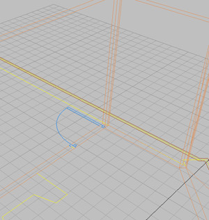
If you look closely at the blue door-swing symbol
that was imported with the floor plan, you'll see that the door
isn't wide enough. Also, the panel in the door defaults to glass,
which isn't necessarily what you want for a bedroom door.
-
 Open
the Modify panel while the door is selected.
Open
the Modify panel while the door is selected. - Change
the width of the door to 3'0”.
-
Click the Quick Render button
again.
The door looks better.
- Scroll
down to the Leaf Parameters rollout and change the Stiles/Top Rail
setting to 6”, the # Panels Horizontal setting
to 2, and the # Panels Vertical setting to 3.
-
Click the Quick Render button
again.
The door is much more detailed.
- In
the Panels group, turn on the Beveled option.
- Click
the Quick Render button once more.
- Save
your work as my_Wall_Door.max.
Experiment by adding more doors to the model.
Some of the closets use the BiFold door type.
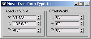
Create AEC Windows:
AEC windows are created in much the same manner
as the AEC doors.
- Continue
using the model from the previous section or open ww_cad_drawing4.max from the \tutorials\designviz folder.
- Ensure
that the Snap Toggle is still active, then right-click it to open
the Grid and Snap Settings dialog.
- Make
sure that Edge/Segment is the only active snap setting and then
close the Grid and Snap Settings dialog.
- Right-click
the name of the Perspective viewports, and choose Wireframe from
the pop-up menu.
-


 If necessary, use
Arc Rotate, Pan and Zoom to display the exterior wall along the
side balcony.
If necessary, use
Arc Rotate, Pan and Zoom to display the exterior wall along the
side balcony.
- Just
as you did for the previous Doors section, hide the A-Wall layer
from the Layers toolbar, if it's not already hidden.
- On
the Create panel, open the Geometry list and choose Windows.
- Choose
Fixed from the Object Type rollout.
Create a single fixed window as wide and deep
as indicated in the template and nearly as tall as the walls.
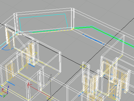
- Using
the imported, blue window as a guide, place the cursor at the base
of the wall at the side of the window nearest the angled, exterior wall.
- With
the Edge snap indicated, click and drag the cursor to the right
(toward the second bedroom), then release to set the width of the window.
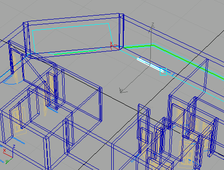
- Move
the cursor over the outside-bottom edge of the wall until the edge
snap indicator is visible. Click to set the depth of the window.
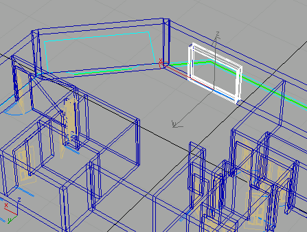
- Drag
the mouse upward, then click to set the height of the window.
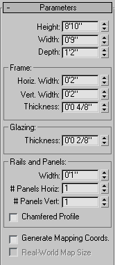
- In
the Parameters rollout set the Height to 8'10”, Width
to 9'0”, and Depth to 1'2”.
- Click
the object color swatch next to the name of the window to open the
Object Color dialog. Select a new color for the window so it isn't
the same blue as the walls.
-
Right-click to end the Fixed window
command and then click the Quick Render button to render the scene.
Now you've added a window into a wall. Next,
you'll make some final adjustments.
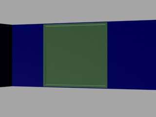
Adjust
the Window:
The window needs a little adjustment to its
positioning and to some of the window characteristics.
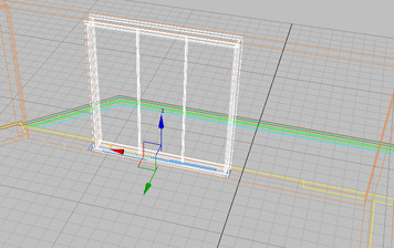
-
 From
the main toolbar, click the Select and Move button and then right-click
it to open the Move Transform Type-In dialog.
From
the main toolbar, click the Select and Move button and then right-click
it to open the Move Transform Type-In dialog.
- In
the Offset:World group, enter 1” in the Z
field.
By shifting the window 1” along the Z axis,
the window creates its own opening and leaves a sill.
- From
the Modify panel, in the Parameters rollout, set the # Panels Horizontal
value to 3 to place three vertical mullions
in the window.
- Experiment
by creating the floor-to-ceiling window on the angled wall. Set
the same height and width and use the Move tool to shift the window
along the Z axis as you did before.
- From
the Layer toolbar, open the Layer list and turn on the A-Wall layer.
You'll need it visible for the next part of
the tutorial.
- Save
the scene as my_Wall_Window.max.
With the window additions completed, you can
go on to build the floor, ceiling and column.
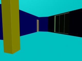
Create the Floor, Ceiling and Column:
Building the floor, ceiling and column demonstrates
the use of the Extrude modifier to quickly create 3D objects using
a 2D shape as a basis.
- Continue
using the model from the previous section or open ww_cad_drawing5.max from the \tutorials\designviz folder.
- Press
the H key, highlight
the Layer:Floor object from the Select Objects dialog, and then
click Select.
This is the floor perimeter object you created
in AutoCAD at the beginning of this tutorial.
-
On the
Modify panel, expand the Modifier List and choose the Extrude modifier.
- On
the Parameters rollout, set Amount to -1”.
This allows the template to remain visible while
you continue to work.
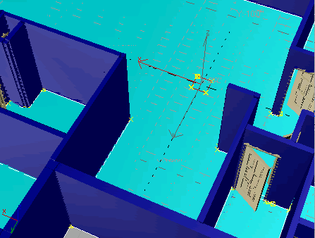
- Select
the Layer:A-Wall object.
-
 Go to
the Spline sub-object level and select the column spline object.
Go to
the Spline sub-object level and select the column spline object.
- In
the Geometry rollout, click the Detach button and name the new object Column.
Click OK.
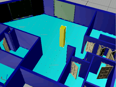
- Turn
off the Spline sub-object mode and select the Column shape.
- Open
the Modifier List and apply an Extrude modifier to the Column. Set
the Amount to 9'0”.
- Select
the Layer:Floor object, choose Edit menu > Clone. On the Clone
Options dialog, turn on Copy in the Object group and name the new
object Ceiling.
- Move
the Ceiling object 9'0” along the Z axis.
- Make
sure the Perspective viewport is active and press the C key.
This changes the Perspective view to a Camera
view.
TipIf
there is no camera in your scene, press Ctrl+C instead
to convert the Perspective view to a new Camera view.
-
Click the Quick Render button
to render the scene.
- Save
your work as my_Apartment.max.
From here, you can start adding materials and
other objects to furnish the flat.