Create the gas source:
In this procedure, you’ll create the source of the gas using Particle Flow.
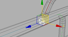
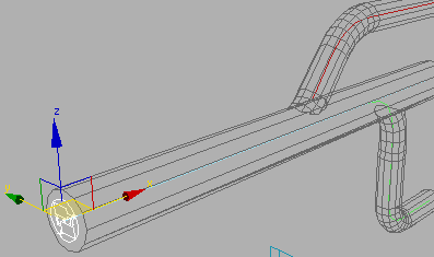
The scene contains a branching tube object, named TubeStructure, set to See-Through so that you can see objects inside the geometry in shaded mode. It also contains three splines that define different paths through the tubes. You’ll create a source for the particles to emit from on the left side or entrance to the tube.
 Go to
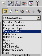
the Create panel. From the drop-down list, choose Particle Systems,
and then click PF Source.
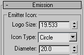
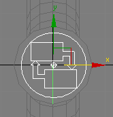
In the Perspective viewport, you can see the PF Source icon displayed as a circle with a logo and an arrow pointing outward from the center of the icon.
Define the default flow:
In this procedure, you’ll start building a flow within Particle View that will describe how particles will behave within the scene. In particular, you’ll define the default flow and direction of the particles.
All particle systems created with Particle Flow use a special editor called Particle View that lets you define the behaviors of particles in a scene. When you create a PF Source icon in your scene, the software automatically creates a standard flow within Particle View. You’ll see this when you first open Particle View.
This opens the Particle View editor in its default arrangement, showing the four main sections: event display, the parameters panel, the depot, and the Description panel.
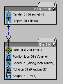
The event display is where you work with operators and events: the components that define particle behavior in a Particle Flow system. The default standard flow consists of a PF Source event and a generic event that contains operators to define a standard stream of particles: Birth, Position, Speed, Rotation, Shape, and Display.
The parameters panel becomes active when you have an action (operator or test) highlighted by clicking it within an event. You can highlight multiple actions to create a stack of parameters for easy access and organization.
The depot is a storage area for all actions available to Particle Flow. You can drag actions from the depot to events; you can also add them via the right-click menu.
The Description panel goes with the depot, although it’s displayed separately. When you click an action in the depot, the Description panel displays a text description of the action's function.
If you play the animation at this early stage, you’ll notice that this standard flow just emits a bunch of particles in the direction of the icon’s arrow from frames 0 to 30.
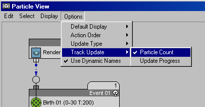
A tab with numbers appears over each event. This is a useful method for seeing how particles are moving through the events within your flow. If you play the animation or drag the time slider, the tab updates with the number of particles in each event. The global event (PF Source 01) shows the total number of particles in the flow, which at this point is the same number of particles as in Event 01.
Notice that each action in an event has some information listed in parentheses next to the action name. This is a quick reference to the action's settings. For example, the Birth operator reads: “Birth01 (0-30 T:200).” This means that it’s a Birth operator set to emit a total of 200 particles from frame 0 to 30. You can verify this by clicking the Birth operator and examining its settings on the Parameters panel.
Also notice that the PF Source 01 event is the initial event and contains only a Render operator. This is because it acts as a global event, defining characteristics of the entire particle flow, not individual events and operators. Any operator in this event is applied globally to all events. You can take advantage of this capability by moving the Display operator to the PF Source event so that no matter which event a particle is in, it will always use the same display method.
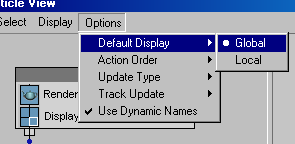
This option prevents Particle View from creating new and unique Display operators for each event.
Change initial settings:


This is the last frame in the animation.
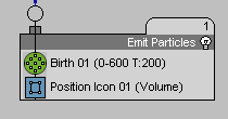
Now the flow is much simpler. You’ve got a global event with Render and Display operators and a single local event with a Birth and a Position event.
If you play the animation now, you’ll see that particles appear on the PF Source icon but don’t go anywhere. That's because in the Emit Particle event, the position of the particles is defined by the Position Icon operator, setting particles to use the volume of the PF Source Icon.