


Autodesk 3ds Max Tutorials > Special Effects > Particle Animation Tutorials > Working with Particle Flow > Visualizing Flow Through Tubes >
Creating Particle Motion
Create particle motion:
In this procedure you’ll use the Speed By Icon operator and a Path constraint to define the motion of particles along a spline through the main tube.
Within an event, a Speed-type operator (Speed, Speed By Icon, Speed By Surface) can give particles velocity: that is, speed and direction. Moving particles along a specific path can be difficult, but luckily there’s a convenient method within Particle Flow. Using the Speed By Icon operator, you can define motion along a path that the particles can follow with a variety of controls.
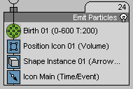
This adds a Speed By Icon operator to the bottom of the event.
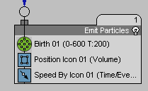
This also automatically creates a new object in your scene at the world origin (0,0,0): a helper object named Speed By Icon 01. If you animate this icon, the particles can inherit its motion.
The Speed By Icon helper object appears at the world origin.
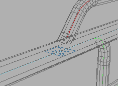
If you move the mouse in the viewport, you can see a rubber-band dashed line connecting the icon to the mouse cursor. The software is requesting a path (spline) to follow.

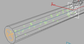
The Speed By Icon 01 icon is now constrained to the PathMain spline over the course of the animation and is oriented perpendicular to the spline. If you play the animation at this point you’ll see that the particles explicitly follow the Speed By Icon 01 helper object.

This will allow the particles to reference the animation of the icon regardless of when they were emitted, as long as they are still contained within the Emit Particles event.
Turn the particles into arrows:
In this procedure you’ll use the Shape Instance and Display operators to cause the particles to appear in the scene as arrow-shaped objects.
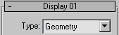
The flow currently contains Render and Display operators, but there isn’t any geometry assigned to the particles. The particles appear in the viewports as arbitrary shapes, but they don’t render at all. You can use the Display operator to change the way in which particles appear.
The particles now appear as X shapes. Particle Flow uses this display method to indicate an error when it is trying to display particles as geometry, but there is no geometry to display. To resolve this, you'll define the geometry for particles that are in the Emit Particles event.
The Shape Instance operator lets you use mesh objects in your scene as particles. With the non-event-driven particle systems such as PArray, you can only use one object at a time, but Shape Instance enables more flexibility by letting you assign groups of objects and cycle through them as particles are emitted.
The name “ArrowMesh” appears on the button.
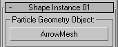
You’ve now defined the ArrowMesh object to be the geometry all particles will use within the Emit Particles event. Because you previously set the Display operator to Geometry, you should now see ArrowMesh particles when you play the animation. They’re too big and not aligned properly, but both conditions are easy to fix.
To make the particles smaller, you could assign a Scale operator, or you could just scale the ArrowMesh object itself, but Shape Instance includes some scaling options to save you a step.
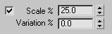
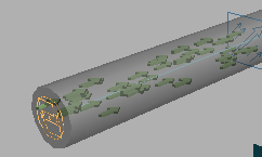
Now the arrows are smaller and fit within the tube without crowding.
Next, you'll adjust the arrows' alignment.
This adds a Rotation operator to the bottom of the Emit Particles event that you can use to specify the orientation of particles in the event.
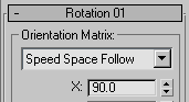
This forces the particles to constantly orient themselves in the direction they are traveling. Particle Flow provides two Speed Space methods: Speed Space sets the orientation once, when each particle first enters the event, while Speed Space Follow continually adjusts the orientation as particles move through the scene. By default, the three axis values are set to 0.0. However, because the ArrowMesh object is pointing along the X axis, it’s necessary to tell the Rotation operator to rotate particles 90 degrees about the X axis.
If you play the animation now, you should see the arrows moving correctly along the PathMain spline.
Next you'll set up tests that will cause some particles to branch off along the other splines.