


Create Custom Mesh (Legacy) |
|
Create Custom Mesh (Legacy) |
|
Create custom polygon or polyface mesh by specifying vertices.
Specify individual vertices when you create mesh using the 3DMESH, PFACE, and 3DFACE commands.
Understand Legacy Mesh Construction
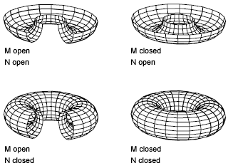
The mesh density controls the number of facets in legacy polygonal and polyface meshes. Density is defined in terms of a matrix of M and N vertices, like a grid consisting of columns and rows. M and N specify the column and row position, respectively, of any given vertex.
A mesh can be open or closed. If the start and end edges of the mesh do not touch, a mesh is open in a given direction, as shown in the following illustrations.
With the 3DMESH command, you can create polygon meshes that are open in both the M and N directions (like the X and Y axes of an XY plane). In most cases, you can use 3DMESH in conjunction with scripts or AutoLISP routines when you know the mesh points.

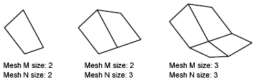
As you create the mesh, you specify the size of the mesh in the M and N directions. The total number of vertices you specify for the mesh is equal to the M value times the N value.
You can close the meshes with PEDIT. You can use 3DMESH to construct irregular meshes.
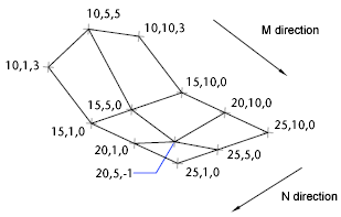
In the following example of text at the Command prompt, you enter the coordinate values for each vertex to create the mesh in the illustration.
Command: 3dmesh
Mesh M size: 4
Mesh N size: 3
Vertex (0, 0): 10,1, 3
Vertex (0, 1): 10, 5, 5
Vertex (0, 2): 10,10, 3
Vertex (1, 0): 15,1, 0
Vertex (1, 1): 15, 5, 0
Vertex (1, 2): 15,10, 0
Vertex (2, 0): 20,1, 0
Vertex (2, 1): 20, 5, -1
Vertex (2, 2): 20,10 ,0
Vertex (3, 0): 25,1, 0
Vertex (3, 1): 25, 5, 0
Vertex (3, 2): 25,10, 0
The PFACE command produces a polyface (polygon) mesh, with each face capable of having numerous vertices. PFACE is typically used by applications rather than by direct user input.
Creating a polyface mesh is like creating a rectangular mesh. To create a polyface mesh, you specify coordinates for its vertices. You then define each face by entering vertex numbers for all the vertices of that face. As you create the polyface mesh, you can set specific edges to be invisible, assign them to layers, or give them colors.
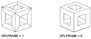
To make the edge invisible, enter the vertex number as a negative value. For instance, to make the edge between vertices 5 and 7 invisible in the following illustration, you enter the following:
Face 3, vertex 3: -7
In the illustration, face 1 is defined by vertices 1, 5, 6, and 2. Face 2 is defined by vertices 1, 4, 3, and 2. Face 3 is defined by vertices 1, 4, 7, and 5, and face 4 is defined by vertices 3, 4, 7, and 8.
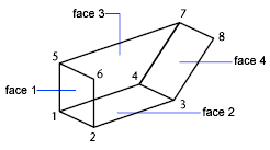
You can control the display of invisible edges with the SPLFRAME system variable. If SPLFRAME is set to a nonzero value, the invisible edges become visible and can then be edited. If SPLFRAME is set to 0, the invisible edges remain invisible.
Create Polyface Mesh Vertex by Vertex
With the 3DFACE command, you can create three-dimensional polyface mesh by specifying each vertex. You can control visibility of each mesh edge segment.
If you select a 3DFACE object during some mesh smoothing operations (such as with MESHSMOOTHMORE), you are prompted to convert 3DFACE objects to mesh objects.
The 3D command creates the following 3D shapes: boxes, cones, dishes, domes, meshes, pyramids, spheres, tori (donuts), and wedges.
In the following illustrations, the numbers indicate points you specify to create the mesh.
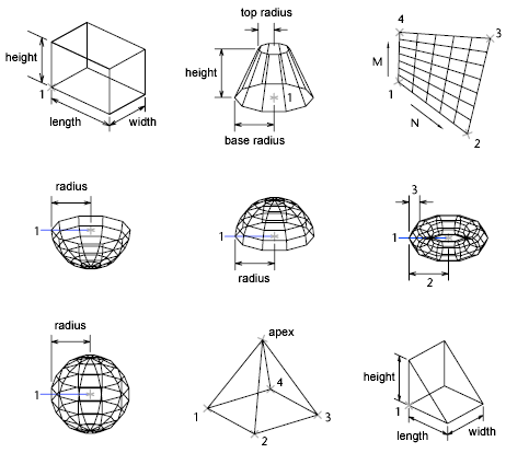
To view the objects you are creating with the 3D command more clearly, set a viewing direction with 3DORBIT, DVIEW, or VPOINT.
 Expand All
 Collapse All


