This describes how to assign TRXs to a cell and how to assign frequencies to TRXs.
When configuring the attributes of TRXs in a cell, assign TRXs for the cell, and then assign frequencies for TRXs, as shown in Figure 1.
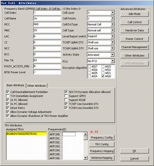
- Assigned TRXs: TRXs that are assigned to the cell.
 NOTE:
NOTE: Different types of BTSs are assigned different numbers of TRXs. For details, see BTS Combined Cabinets and Cabinet Groups.
- Frequencies: frequencies that can be assigned to the TRXs. For non-FH cell, each TRX is assigned one frequency to process services.
The BSC supports frequency bands GSM900, DSC1800, GSM900&DCS1800, GSM850, PCS1900, GSM850&DCS1800, and GSM850&PCS1900. Different frequency bands correspond to different frequency ranges. Table 1 lists frequency bands and their corresponding frequency ranges.
Frequency Band |
Frequency Range |
|---|---|
GSM900 |
0-124, 955-1023 |
DCS1800 |
512-885 |
GSM900&DCS1800 |
0-124, 512-885, 955-1023 |
GSM850 |
128-251 |
PCS1900 |
512-810 |
GSM850&DCS1800 |
128-251, 512-885 |
GSM850&PCS1900 |
128-251, 512-810 |
When the BSC Abis interface board is connected to the BTS in different transmission modes, the number of TRXs provided by each E1 port on the BSC Abis interface board varies. The principles are as follows:
BTS in TDM transmission mode
When the BTS local switching and the Flex Abis mode are not used, each E1 port supports 13 to 15 TRXs. When all the TRXs on the E1 port of the Abis interface board carry the TCHFs, each E1 port supports 15 TRXs; when all the TRXs on the E1 port of the Abis interface board carry the TCHHs, each E1 port supports 13 TRXs.
When the BTS local switching and the Flex Abis mode are used, each E1 port supports 13 to 18 TRXs.
BTS in HDLC transmission mode
Each E1 port supports 20 to 24 TRXs. When all the TRXs on the E1 port of the Abis interface board carry the TCHFs, each E1 port supports 24 TRXs; when all the TRXs on the E1 port of the Abis interface board carry the TCHHs, each E1 port supports 20 TRXs.