This describes how to add a common BTS in IP transmission mode for the BSC, and how to configure the site device attributes, cell basic attributes, and TRX attributes.
| Scenario | BSC initial configuration and BSC capacity expansion |
| Mandatory/Optional | Mandatory |
The BTS in IP transmission mode does not support the Ring Mode , Config AbisByPass or Backup OML function, and does not support cascading configuration.
Only the BTS3012, BTS3012AE, and BTS3012 II support the IP transmission mode.
The BTS in IP transmission mode cannot extract clock from the BSC directly. Its clock is provided by the IP clock server.
The BTS in IP transmission mode supports the device IP address and the port IP address. Select a specific transmission mode by setting BTS Communication Type. On the LMT, the port IP address of the BTS is used for transmission by default. When the device IP address is used in communication, the BTS routes must be configured; when the port IP address is used in communication, you do not need to configure the BTS routes.
Prerequisites
- The GFGUB/GOGUB is configured. If the GFGUB/GOGUB is in active/standby mode, the device IP addresses and port IP address for the active and standby boards are configured. For details, see Configuring the GFGUB/GOGUB.
- The GXPUM/GXPUT is configured for the GMPS or GEPS where the GFGUB/GOGUB is located. For details, see Configuring the GXPUM and Configuring the GXPUT.
Preparation
The following procedure takes how to add a BTS on the GFGUB in the GEPS as an example.
Parameter |
Example |
Source |
|
|---|---|---|---|
BTS Attributes |
BTS Name |
BTS 1 |
Network planning |
Site Type |
BTS3012 |
Network planning |
|
Upper-Level Port No. |
0 GFGUB Port |
Network planning |
|
Service Mode |
IP |
Network planning |
|
BTS IP |
172.20.7.40 |
Network planning |
|
BTS IP Mask |
255.255.255.0 |
Network planning |
|
Active |
Deselected |
Network planning |
|
Cell attributes |
Cell Name |
Cell 1 |
Network planning |
Frequency Band |
GSM900 |
Network planning |
|
MCC |
460 |
Network planning |
|
MNC |
01 |
Network planning |
|
LAC |
8240 |
Network planning |
|
CI |
1 |
Network planning |
|
BCC |
1 |
Network planning |
|
NCC |
1 |
Network planning |
|
Cell Extension Type |
Common cell |
Network planning |
|
Cell Type |
Common cell |
Network planning |
|
TRX Attributes |
Assigned Cell |
Cell 1 |
Network planning |
Frequency configuration |
988 (main BCCH frequency), 994 |
Network planning |
|
TRX configuration |
TRX 0, TRX 1 |
Network planning |
|
Hop Mode |
None |
Network planning |
|
PTU attributes |
Physical IP Address of Ethernet Port 1 |
172.20.6.40 |
Network planning |
Physical IP Mask of Ethernet Port 1 |
255.255.255.0 |
Network planning |
|
Port Rate |
10M |
Network planning |
|
Main PTU Bar Code |
0000000000000001 |
BTS internal planning |
|
Back PTU Bar Code |
0000000000000002 |
BTS internal planning |
|
IP Clock Port |
33003 |
BTS internal planning |
|
Abis MUX Global Enable Switch |
Open |
Network planning |
|
BTS Communication Type |
Port IP |
Network planning |
|
Peer Port IP address index |
0 |
Network planning |
|
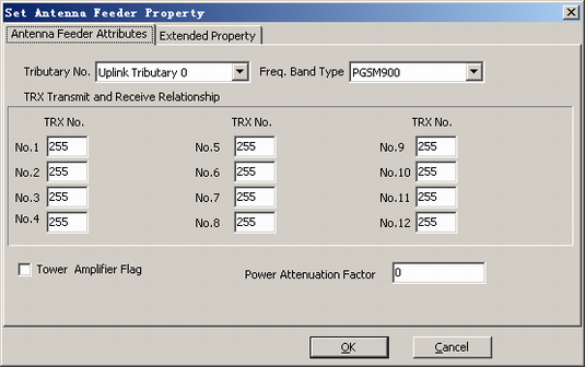
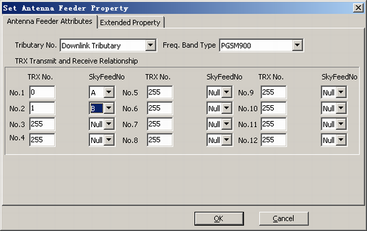
Antenna feeder attributes |
Tributary No. |
Downlink Tributary |
Network planning |
Frequency Band |
PGSM900 |
Network planning |
|
TRX Transmit and Receive Relationship |
TRX No.1: 0, A TRX No.2: 1, B |
Network planning |
|
Procedure
- On the BSC6000 Local Maintenance Terminal, right-click the GFGUB in the GEPS.
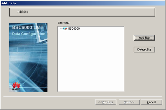
- Choose . A dialog box is displayed, as shown in Figure 1.
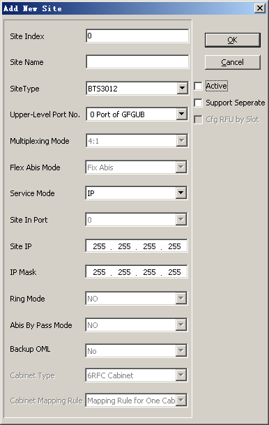
- Click Add Site. A dialog box is displayed, as shown in Figure 2.
- Set the parameters by referring to Table 1.
 NOTE:
NOTE: The Support Separate option is available only for the BTS3012, BTS3012 II, and BTS3012AE. If Support Separate is selected, the BTS3012, BTS3012 II, and BTS3012AE can be configured with the DTRU/QTRU.
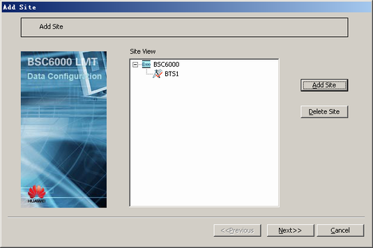
- Click OK. A dialog box is displayed, as shown in Figure 3.
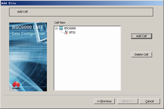
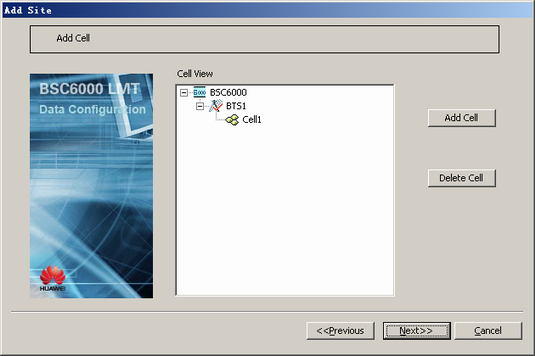
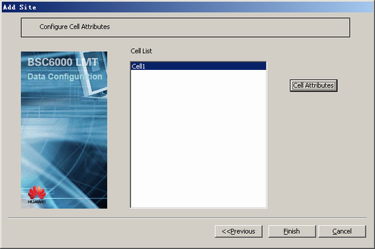
- Click Next. A dialog box is displayed, as shown in Figure 4.
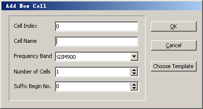
- Select a BTS, and then click Add Cell. A dialog box is displayed, as shown in Figure 5.
- Set the parameters by referring to Table 1. NOTE:
To add multiple cells at a time, set Number of Cells. The added cells are named in the form of current Cell Name + sequence number.
- Click OK. A dialog box is displayed, as shown in Figure 6.
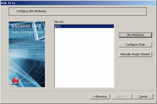
- Click Next. A dialog box is displayed, as shown in Figure 7.
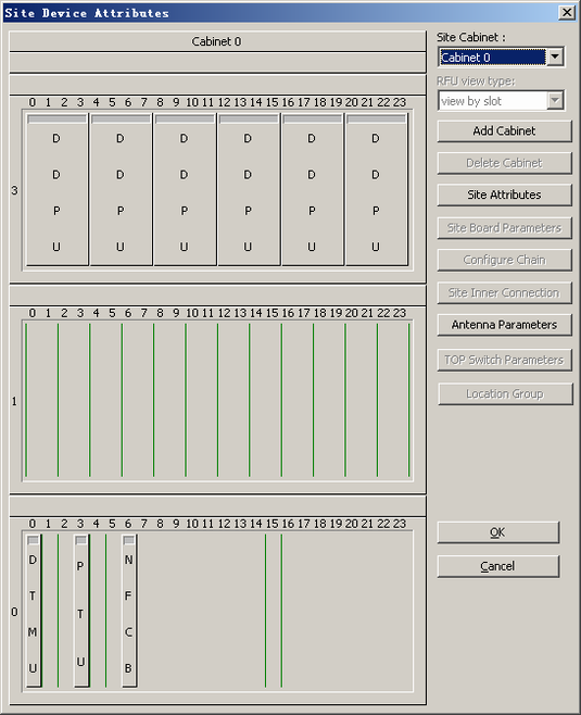
- Click Site Attributes. A dialog box is displayed, as shown in Figure 8.
- Double-click DDPU. A dialog box is displayed, as shown in Figure 9.
NOTE:
- This takes the configuration of one antenna feeder port on the DDPU as an example. If the antenna feeder port is not required, you can delete the DDPU.
- You have to specify at least one TRX for the downlink tributary of the DDPU. For other tributaries, use the default settings.
- The DDPU has two paths: A and B. The two paths are independent of each other. The data configurations of the DDPU must be consistent with the physical connections, and the frequency band of the TRX must be the same as the frequency band of the DDPU.
- Set the parameters by referring to Table 1, as shown in Figure 10.
- In the dialog box shown in Figure 8, right-click an empty slot in the DTRU and choose from the shortcut menu. A TRU is added.
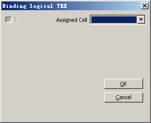
- Right-click the added TRU and choose from the shortcut menu. A dialog box is displayed, as shown in Figure 11.
- Set Assigned Cell by referring to Table 1.
- Click OK to return to the dialog box shown in Figure 8.
- Repeat 14 through 17 to configure more TRUs.
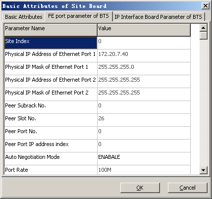
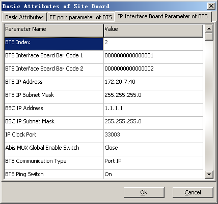
- Right-click a PTU in the common subrack and choose from the shortcut menu. A dialog box is displayed, as shown in Figure 12.
- Click the FE port parameter of BTS tab to display the tab page, as shown in Figure 13.
- Set the parameters by referring to Table 1. NOTE:
BTS3012, BTS3012AE, BTS3012_II, DBS3900, BTS3900, BTS3900A, BTS3900B, and BTS3900E do not support that Muplex Mode is set to HALF.
The parameter Peer Port IP address index specifies the index of the valid IP address for a BSC port. The BSC supports the setting of multiple IP address under one Port No.. The Peer Port IP address index maps the valid IP address of the BSC port. After the value of Peer Port IP address index is specified, the BSC IP Address in the IP Interface Board Parameter of BTS tab page is generated automatically and the BSC IP Address cannot be changed.
- Click the PTU parameter of BTS tab to display the tab page, as shown in Figure 14.
- Set the parameters by referring to Table 1. NOTE:
You can obtain the BTS Interface Board Bar Code by running the DSP BTSESN command.
- Click OK to return to the dialog box shown in Figure 8.
- Repeat 19 through 24 to configure the attributes of more PTUs.
- Click OK to return to the dialog box shown in Figure 7.
- Click Next. A dialog box is displayed, as shown in Figure 15.
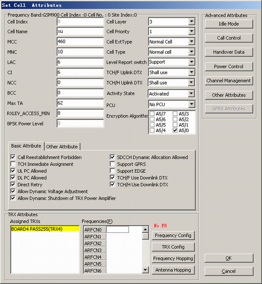
- Click Cell Attributes. A dialog box is displayed, as shown in Figure 16.
- Set the basic attributes of the cell by referring to Table 1. NOTE:
- For two cells, the values of at least one of the following parameters should be different: MCC, MNC, LAC, and CI.
- If you select GPRS Support, the BSC must be configured with the built-in PCU. If the BTS does not support the GPRS function or the GPRS services are unavailable in the cell, do not select GPRS Support.
- Click OK to return to the dialog box shown in Figure 15.
- Click Finish. The configuration of the BTS is complete.
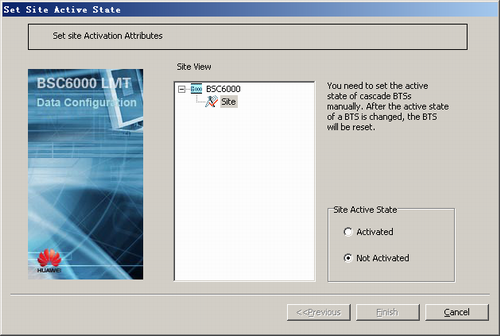
- Activating a BTS.
- On the Management Tree tab page of the BSC6000 Local Maintenance Terminal, right-click the target BTS and choose from the shortcut menu. A dialog box is displayed, as shown in Figure 17.