This describes how to configure the TDM over Packet (TOP) switching parameters on the backplane to share the E1/T1 timeslots between the GSM network and the UMTS network. That is, the E1/T1 timeslots in the GSM and UMTS networks can be shared.
| Scenario | BSC initial configuration and BSC capacity expansion |
| Mandatory/Optional | Optional |
Prerequisite
Working Standard of the BTS is GSM&UMTS. The TRX board types are MRRU and MRFU.
The DBS3900 GSM, BTS3900 GSM, BTS3900A GSM, DBS3036, BTS3036, and BTS3036A support the TOP switching parameters.
Preparation
The following procedure takes how to configure the TOP switching parameters on the DBS3900 GSM as an example.
Parameter |
Description of the Configuration |
Example |
|---|---|---|
E1 Port No. |
Number of the virtual E1/T1 port on the backplane of the BBU. The value range is 16-19. |
16 |
TOP Board Slot No. |
Slot number configured for the UMTS controlling board that shares the E1/T1 timeslots with the GTMU. |
7 |
Port Type |
The port has two types: Out Port and In Port.
When the GSM uses certain E1/T1 timeslots of the UMTS, the Port Type of the GSM is set to In Port. When the UMTS uses certain E1/T1 timeslots of the GSM, the Port Type of the GSM is set to Out Port. |
Out Port |
Switch Source E1/T1 Port No. |
Number of the E1/T1 port on the GTMU panel. The value range is 0 to 7.
|
2 |
Timeslot Mask |
Numbers of E1/T1 timeslots shared by the GSM and UMTS networks.
|
16, 17, 18, and 19 |
Procedure
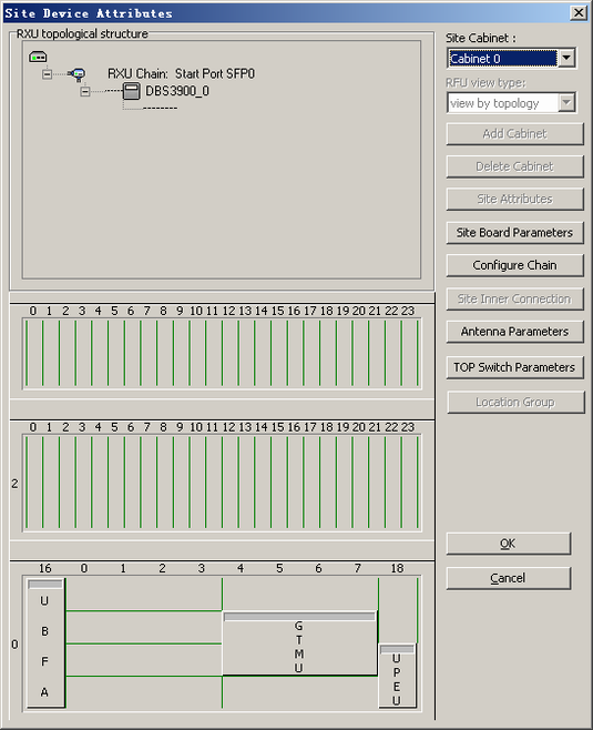
- On the Management Tree tab page of the BSC6000 Local Maintenance Terminal, right-click a BTS and then choose Configure Site Board Attributes from the shortcut menu. In the displayed dialog box, click Configure Site Board Attributes. A dialog box is displayed, as shown in Figure 1.
- Click TOP Switch Parameters. A dialog box is displayed, as shown in Figure 2.
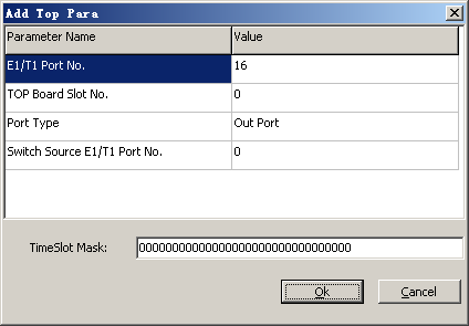
- Click Add Record. A dialog box is displayed, as shown in Figure 3.
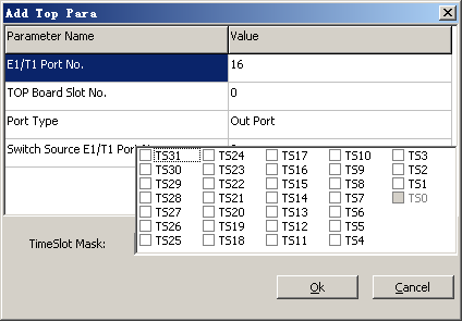
- Set the parameters by referring to Table 1. To configure the timeslot mask, click the TimeSlot Mask text box and select the related timeslot on the displayed page shown in Figure 4.
- Repeat 3 through 4 to set the TOP switching parameters for more E1/T1 ports.
- Click OK to return to the dialog box, as shown in Figure 2.
- Click OK to return to Figure 1. Click OK to return to the upper-level menu. Then, click Finish.