This describes how to configure the customized alarms of the base station, which involves defining the alarm port, defining the alarm ID, and defining the alarm name.
| Mandatory/Optional | Mandatory |
Preparation
The data listed in Table 1 should be obtained before you configure the environment alarms.
Table 1 Example of the data negotiated and planned for configuring environment alarms Parameter
Example
Source
Board Type
UPEU
BSC internal planning
Alarm Port
ALM-1
Color of Wire on the Alarm Port
Orange and white/Orange
Alarm Shield Flag
3
Alarm Voltage Definition
2
Port No.
13
Alarm ID
65527
Switch
OPEN
Port Type
BOOL
Site Name
BTS3900
Subrack No.
0
Slot No.
6
Alarm Name
Fire
Alarm Severity
Critical
Event Type
Environment
 NOTE:
NOTE: Each type of environment alarms should be allocated with a unique alarm ID. For the environment alarm input port of the BTS, the value range of the alarm IDs is 65384-65533.
- Ensure that the board and cables related to the external alarm signals are installed.
- Ensure that the board related to the external alarm signals is configured on the LMT.
Procedure
- Configure the customized alarm.
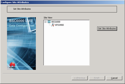
- On the BSC6000 Local Maintenance Terminal, right-click the target BTS and choose from the shortcut menu. A dialog box is displayed, as shown in Figure 1.
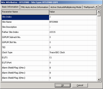
- Choose Set Site Attributes. A dialog box is displayed, as shown in Figure 2.
- On the Basic Information tab page, set Alarm Shield Flag and Alarm Voltage Definition. NOTE:
- Alarm Shield Flag 1 (hexadecimal, 8 bits for Boolean signals 0 to 7), Alarm Shield Flag 2 (hexadecimal, 8 bits for Boolean signals 8 to 15), and Alarm Shield Flag 3 (hexadecimal, 8 bits for Boolean signals 16 to 23) can be set. Each alarm shield flag represents eight Boolean signals (most significant bits on the left and least significant bits on the right). Therefore, there are a total of 24 Boolean signals. If the bit is set to 0, the Boolean signal is shielded, and the alarm is not reported. If the bit is set to 1, the Boolean signal is not shielded, and the alarm can be reported
- Alarm Voltage Definition 1 (hexadecimal, 8 bits for Boolean signals 0 to 7), Alarm Voltage Definition 2 (hexadecimal, 8 bits for Boolean signals 8 to 15), and Alarm Voltage Definition 3 (hexadecimal, 8 bits for Boolean signals 16 to 23) can be set. Each alarm voltage definition represents eight Boolean signals (most significant bits on the left and least significant bits on the right). Therefore, there are a total of 24 Boolean signals. If the bit is set to 0, the voltage level of the Boolean signal is low. If the bit is set to 1, the voltage level of the Boolean signal is high.
- Configure the alarm port.
- Obtain the related alarm port No. by referring to Customized Alarm Ports of the DBS3900/BTS3900/BTS3900A Base Station. For example, the port No. corresponding to the orange and white/orange wires on ALM-1 of the UPEU is 13. NOTE:
- The Alarm ID in "Customized Alarm Ports of the 3900 Series Base Station" is the BTS internal alarm ID instead of the BSC alarm ID.
- Assume that the orange and white/orange wires on ALM-1 of the UPEU in the BBU are used to transport the fire alarm signals of the telecommunications room, and the planned fire alarm ID is 65527. Taking this as the example, the following procedure describes how to configure the parameters related to the external alarm.
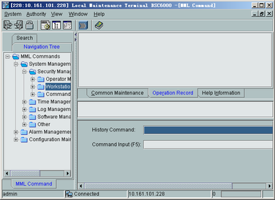
- On the toolbar of the BSC LMT, click
 . The Local Maintenance Terminal BSC6000-[MML Command] window is
displayed, as shown in .
. The Local Maintenance Terminal BSC6000-[MML Command] window is
displayed, as shown in .
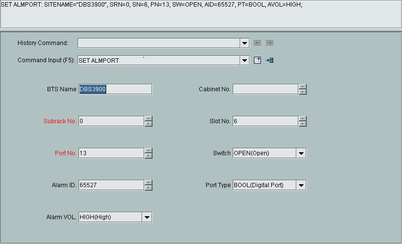
- Enter the SET ALMPORT command in the Command Input box and then click the "Generate Input Interface" button
 . The parameter interface is displayed, as shown in Figure 4.
- Set the parameters according to Table 1. NOTE:
- The Boolean alarms related to the UPEU and UEIU are reported through the GTMU. Therefore, set Subrack No. and Slot No. of the UPEU and UEIU to the subrack and slot numbers of the GTMU.
- It is unnecessary to set Cabinet No..
- After the parameter setting, click the
 button. The setting of the Boolean alarm port is complete.
- Obtain the related alarm port No. by referring to Customized Alarm Ports of the DBS3900/BTS3900/BTS3900A Base Station. For example, the port No. corresponding to the orange and white/orange wires on ALM-1 of the UPEU is 13.
- Configure the environment alarm.
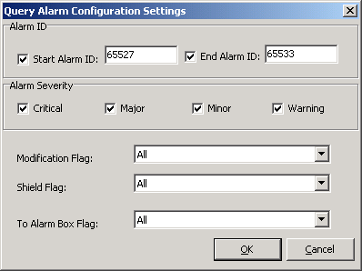
- On the BSC6000 Local Maintenance Terminal, choose . A dialog box is displayed, as shown in Figure 5.
- According to the alarm ID to be queried, set Start Alarm ID and End Alarm ID. NOTE:
For the environment alarm input port of the BTS, the value range of the alarm IDs is 65384-65533.
- Click OK. A dialog box is displayed, as shown in Figure 6.
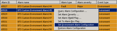
- Right-click the alarm ID to be queried. The shortcut menu is displayed, as shown in Figure 7.
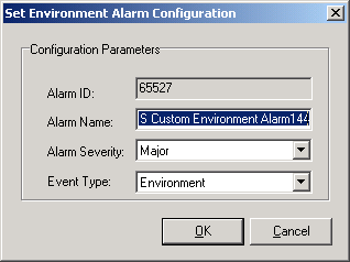
- Choose Set Environment Alarm Configuration. A dialog box is displayed, as shown in Figure 8.
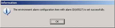
- Click OK. If the parameter setting is successful, a dialog box is displayed, as shown in Figure 9.